A
Amy KirkAug 4, 2025
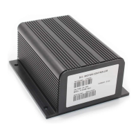
What to do if my Curtis MultiMode 1215-8 vehicle does not move forward?
- IibakerAug 4, 2025
If your Curtis Controller-equipped vehicle isn't moving forward, the issue might be with the forward switch or its wiring. Inspect the forward switch and wiring, and replace if necessary. After that, re-test the vehicle. If the programmer indicates the forward switch is closing and the vehicle now moves as expected, the problem is resolved.