Curtis 1214-/15-/19-8 Manual 4
CONNECTIONS: Low Current
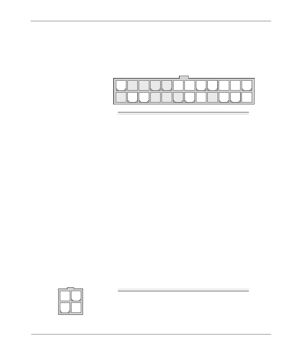
A 24-pin low current connector in the front of the controller provides the low
current logic control connections (see pin list below). The mating connector is
Molex Mini-Fit Jr., part number 39-01-2245. Contact Molex regarding compat-
ible pins: 39-00-0078 for #16 AWG, 39-00-0039 for #18–24 AWG.
2 — INSTALLATION & WIRING
Pin 1 keyswitch input (KSI)
Pin 2 brake input
Pin 3 mode selection input
Pin 4 n/c
Pin 5 throttle: 0–10V
Pin 6 emergency reverse input
Pin 7 n/c
Pin 8 n/c
Pin 9 n/c
Pin 10 forward input
Pin 11 reverse input
Pin 12 n/c
Pin 13 throttle: 3-wire pot high
Pin 14 throttle: pot low
Pin 15 throttle: 0–5V (3-wire pot wiper)
Pin 16 throttle: 2-wire 5kΩ–0 or 0–5kΩ input
Pin 17 main contactor driver output
Pin 18 forward contactor driver output
Pin 19 reverse contactor driver output
Pin 20 n/c
Pin 21 n/c
Pin 22 n/c
Pin 23 n/c
Pin 24 emergency reverse (BB) check output [optional]
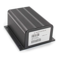
A 4-pin low power connector, also located on the front of the controller, is
provided for the handheld programmer.
24 23 22 21 20 19 18 17 16 15 14 13
121110987654321