Curtis 1214-/15-/19-8 Manual 10
0–5V Throttle
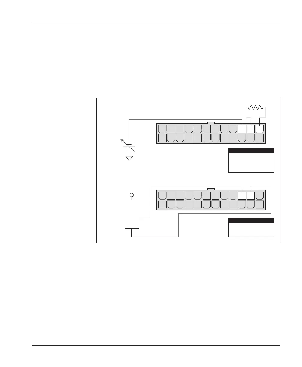
Two ways of wiring the 0–5V throttle are shown in Figure 7. Broken wire
protection is provided by the controller looking for a minimum current into the
Pot Low pin. If the Pot Low input current falls below 0.1 mA, a throttle fault is
generated and the controller is disabled. If a throttle sensor is used, the sensor’s
ground return current must be less than 10 mA. If the 0–5V throttle input (Pin
15) exceeds 8 volts, the controller output will be disabled. NOTE: In Figure 7(a),
the throttle’s voltage input signal is in reference to Pot Low.
2 — INSTALLATION & WIRING
0–10V Throttle
Two ways of wiring the 0–10V throttle are shown in Figure 8. Broken wire
protection is provided by the controller looking for a minimum current into the
Pot Low pin. If the Pot Low input current falls below 0.1 mA, a throttle fault is
generated and the controller is disabled. If a throttle sensor is used, the sensor’s
ground return current must be less than 10 mA. If the 0–10V throttle input (Pin
5) exceeds 16 volts, the controller output will be disabled. NOTE: In Figure 8(a),
the throttle’s voltage input signal is in reference to Pot Low.
Fig. 7 Wiring for 0–5V
throttle (“Type 2”).
(b) 0–5V throttle sensor
(a) Ground-referenced 0–5V throttle
14 1315161718192021222324
121110987654321
14 1315161718192021222324
121110987654321
SENSOR OUTPUT
SENSOR GROUND
0–5V
SENSOR
+
+
-
B-
4.7 kΩ
(Shunt impedance 150 k
Ω
to ground)
Pin 15
Pin 14
Pin 13
0–5V Input
Pot Low
Pot High
PIN KEY
Pin 15
Pin 14
0–5V Input
Pot Low
PIN KEY