Curtis 1214-/15-/19-8 Manual 8
WIRING: Throttle
Wiring for various throttles is described below. These include 5kΩ–0 and 0–5kΩ
throttles, 0–5V and 0–10V throttles, 3-wire potentiometer throttles, and elec-
tronic throttles. If the throttle you are planning to use is not covered, contact the
Curtis office nearest you.
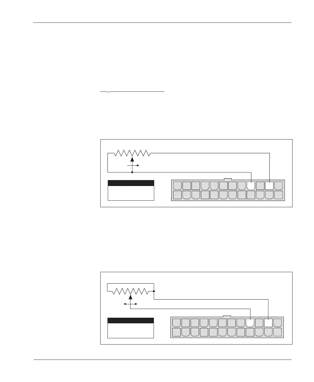
5kΩ–0 Throttle (“Type 1”)
The 5kΩ–0 throttle (called a “Type 1” throttle in the programming menu of the
handheld programmer) is a 2-wire resistive throttle that connects between the
2-Wire Pot pin (Pin 16) and the Pot Low pin (Pin 14), as shown in Figure 4. It
doesn’t matter which wire goes on which pin. For Type 1 throttles, zero speed
corresponds to 5kΩ and full speed corresponds to 0Ω.
2 — INSTALLATION & WIRING
Fig. 4 Wiring for 5k
Ω
–0
throttle (“Type 1”).
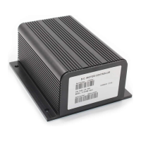
In addition to accommodating the basic 5kΩ–0 throttle, the Type 1 throttle
input can be used to implement a wigwag-style throttle. Using a 20kΩ potenti-
ometer wired as shown in Figure 5, the pot wiper can be set such that the
controller has 5kΩ between Pins 14 and 16 when the throttle is in the neutral
position. The throttle mechanism can then be designed such that rotating it
either forward or back decreases the resistance between Pins 14 and 16, which
increases the controller output. The throttle mechanism must provide signals to
Fig. 5 Wiring for 20k
Ω
potentiometer used as a
wigwag-style throttle
(“Type 1”).
14 1315161718192021222324
121110987654321
Pin 16
Pin 14
2-Wire Pot
Pot Low
PIN KEY
20 kΩ
FASTERFASTER
14 1315161718192021222324
121110987654321
Pin 16
Pin 14
2-Wire Pot
Pot Low
PIN KEY
5kΩ–0
FASTER