Curtis 1214-/15-/19-8 Manual 7
Standard Power Wiring
In every wiring configuration, it is imperative that the field be wired between B+
and A2 and that the armature be wired between M- and the A2 terminal. The
internal plug diode used in the 1214-/15-/19-8 is connected between M- and A2.
Therefore, the armature and field positions cannot be interchanged. Reversing
contactors can be used to switch either the armature or the field.
Standard Control Wiring
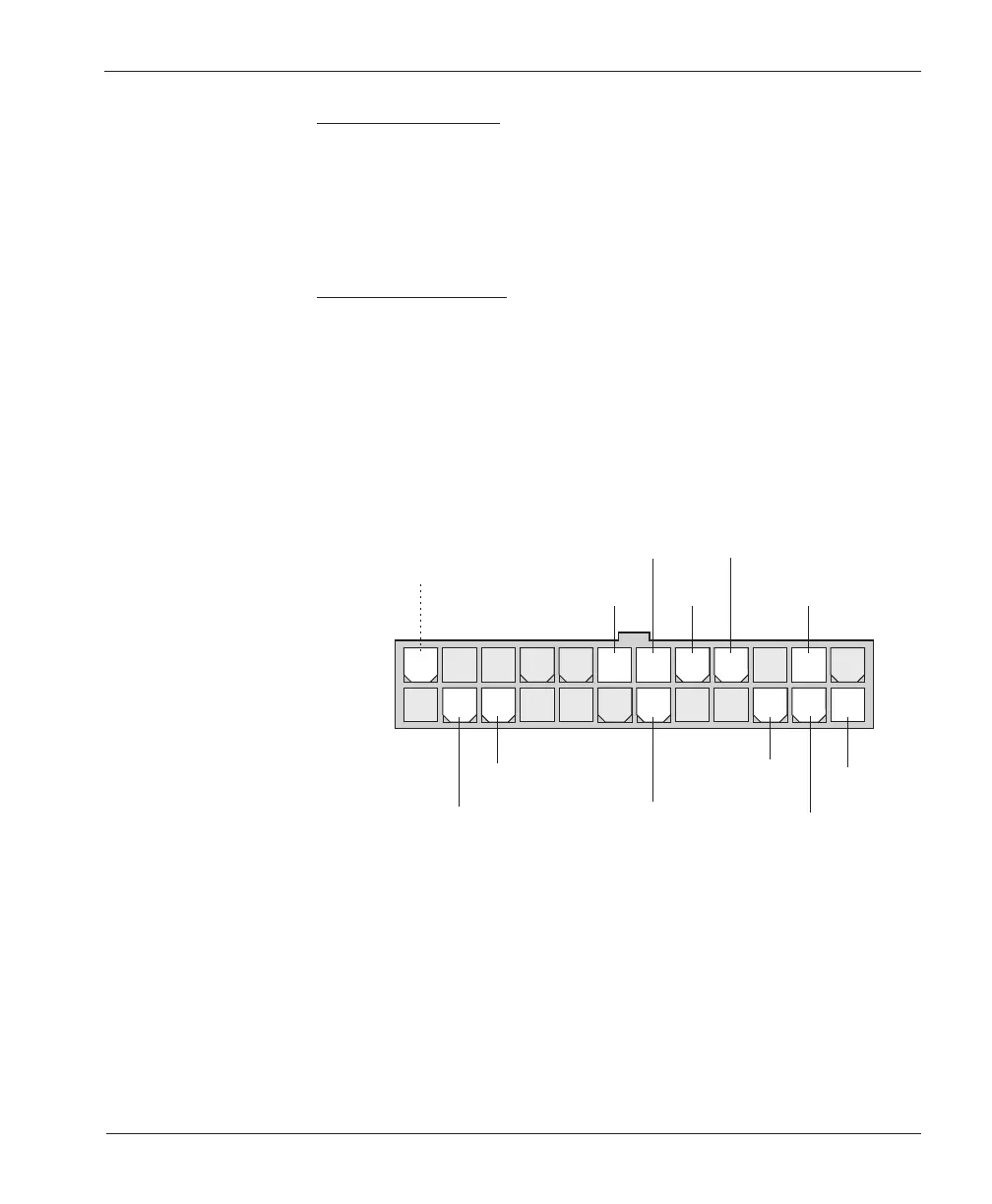
Wiring for the input switches and contactors is shown in Figure 3 (see detail
below). The main contactor, if one is used, is normally connected directly to the
controller. Optionally, the main contactor can be switched directly by the
keyswitch or brake, leaving Pin 17 unconnected.
The throttle shown in Figure 3 is a 5kΩ–0 type. Various other throttles can also
be accommodated, and are discussed in the throttle wiring section.
2 — INSTALLATION & WIRING
24-pin detail (see Fig. 3):
MODE
SELECT
FORWARD
KEYSWITCH
EMERGENCY
REVERSE
CHECK
OUTPUT
(factory option)
BRAKE
or
SEAT SWITCH
EMERGENCY
REVERSE
(walkies only)
REVERSE
MAIN
CONTACTOR
REVERSE
CONTACTOR
2-WIRE POT
(5 k
Ω
)
FORWARD
CONTACTOR
POT
LOW
24 23 22 21 20 19 18 17 16 15 14 13
121110987654321