Curtis 1214-/15-/19-8 Manual 11
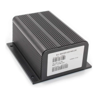
3-Wire Potentiometer (500
Ω
–10k
Ω
) Throttle
The 3-wire potentiometer is used in its voltage divider mode—with the voltage
source and return being provided by the controller. Pot High provides a current-
limited 5V source to the potentiometer, and Pot Low provides the return path.
Wiring is shown in Figure 9.
2 — INSTALLATION & WIRING
Fig. 9 Wiring for 3-wire
potentiometer throttle
(“Type 2”).
As with the 2-wire throttles, broken wire protection is provided by the
controller looking for a minimum current into the Pot Low pin. If the Pot Low
input current falls below 0.1 mA, a throttle fault is generated and the controller
is disabled. NOTE: The Pot Low pin (Pin 14) must not be tied to ground.
14 1315161718192021222324
121110987654321
OFF
ON
500Ω–10kΩ
Pin 15
Pin 14
Pin 13
Pot Wiper
Pot Low
Pot High
PIN KEY
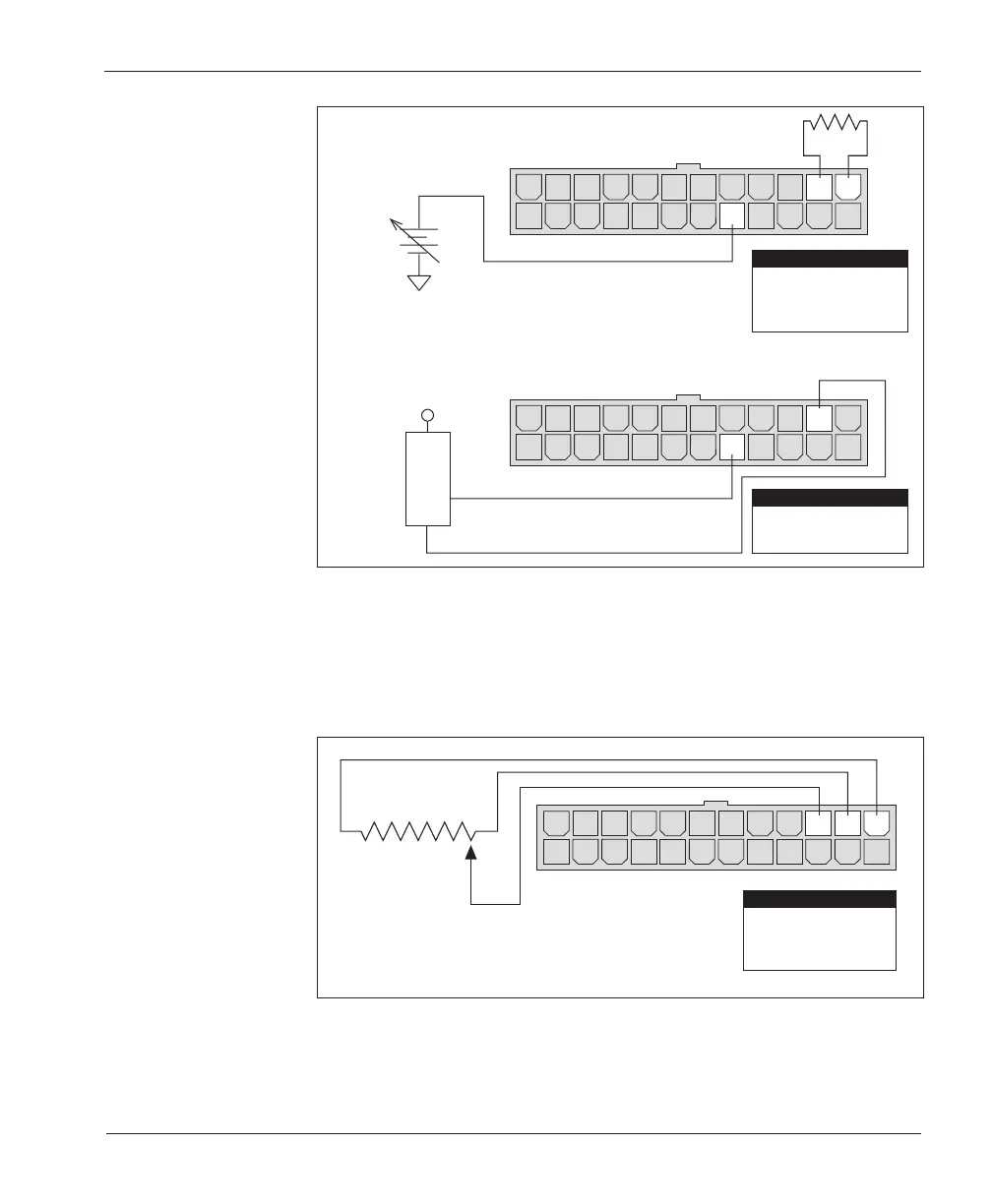
Fig. 8 Wiring for 0–10V
throttle (“Type 2”).
(b) 0–10V throttle sensor
(a) Ground-referenced 0–10V throttle
14 1315161718192021222324
121110987654321
14 1315161718192021222324
121110987654321
SENSOR OUTPUT
SENSOR GROUND
0–10V
SENSOR
+
+
-
B-
4.7 kΩ
Pin 14
Pin 13
Pin 5
Pot Low
Pot High
0–10V Input
PIN KEY
PIN KEY
Pot Low
0–10V Input
Pin 14
Pin 5