Curtis 1214-/15-/19-8 Manual 12
Curtis ET-XXX Electronic Throttle
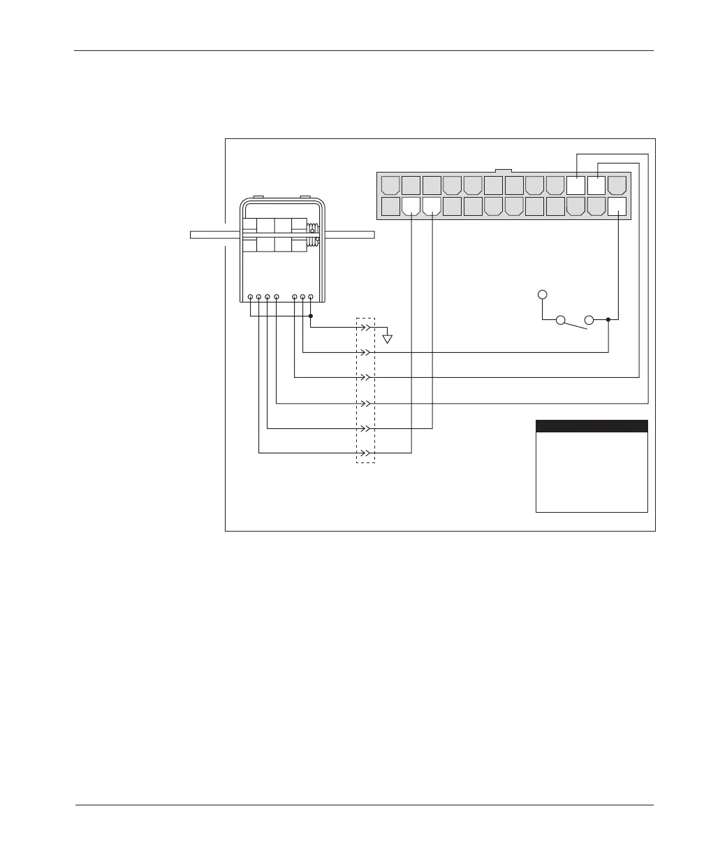
The Curtis ET-XXX provides throttle and forward/reverse inputs; wiring is
shown in Figure 10.
2 — INSTALLATION & WIRING
Fig. 10 Wiring for Curtis
ET-XXX electronic throttle
(“Type 2”).
14 1315161718192021222324
121110987654321
GREEN
ORANGE
BLACK
BLACK/WHITE
WHITE
WHT/BRN
B-
KEYSWITCH
B+
Pin 15
Pin 14
Pin 11
Pin 10
Pin 1
0–5V Input
Pot Low
Reverse
Forward
KSI Input
PIN KEY
WHT/
GRN
WIRING: Emergency Reverse Check
An optional wire connected directly to the emergency reverse (belly button)
switch provides for broken wire detection when that feature is enabled at the
factory. The emergency reverse check output wire periodically pulses the emer-
gency reverse circuit to check for continuity. If there is no continuity, the
controller limits the vehicle to 15% speed and a fault code is indicated.
If the option is selected and the check wire is not connected, the vehicle
speed is limited to 15%. If the option is not selected and the check wire is
connected, no harm will occur—but continuity will not be checked.
The emergency reverse check output wire is connected to Pin 24, as shown
by the dotted line in the basic wiring diagram (Figure 3).