Curtis 1214-/15-/19-8 Manual 21
LED DIAGNOSTICS
During normal operation, with no faults present, the LED on the controller’s
front face flashes a single flash at approximately 1 flash/second. If the controller
detects a fault, a 2-digit code (see Table 2) is flashed continuously until the fault
is corrected. For example, code “3,2”—welded direction contactor—appears as:
¤¤¤ ¤¤ ¤¤¤ ¤¤ ¤¤¤ ¤¤
( 3 , 2 ) ( 3 , 2 ) ( 3 , 2 )
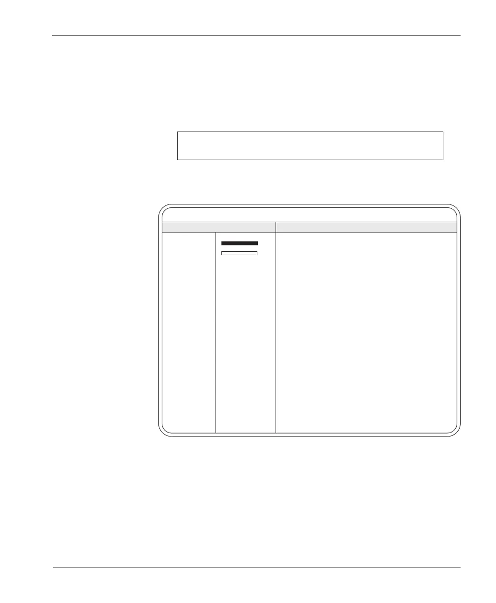
Table 2 LED CODES
LED CODE EXPLANATION
LED off no power or defective controller
solid on defective controller
single flash ¤ controller operational; no faults
1,2 ¤¤¤ hardware fail-safe error
1,3 ¤ ¤¤¤ M- fault or motor output short
1,4 ¤ ¤¤¤¤ sequencing fault (SRO)
2,1 ¤¤ ¤ 5kΩ–0 or throttle wiper input fault
2,2 ¤¤ ¤¤ emerg. rev. circuit check fault (BB wiring)
2,3 ¤¤ ¤¤¤ high-pedal-disable fault (HPD)
2,4 ¤¤ ¤¤¤¤ throttle pot low open or shorted to B+ or B-
3,1 ¤¤¤ ¤ contactor driver overcurrent
3,2 ¤¤¤ ¤¤ welded direction contactor
3,3 ¤¤¤ ¤¤¤ [reserved for future use]
3,4 ¤¤¤ ¤¤¤¤ missing contactor
4,1 ¤¤¤¤ ¤ low battery voltage
4,2 ¤¤¤¤ ¤¤ overvoltage
4,3 ¤¤¤¤ ¤¤¤ thermal cutback
4,4 ¤¤¤¤ ¤¤¤¤ [reserved for future use]
NOTE: Only one fault is indicated at a time, and faults are not queued up.
Operational faults—such as a fault in SRO sequencing—are cleared by cycling
the brake/seat switch or keyswitch. (See “Fault recovery” in Appendix A for more
information.)
5 — DIAGNOSTICS & TROUBLESHOOTING