Curtis 1214-/15-/19-8 Manual 3
INSTALLATION AND WIRING
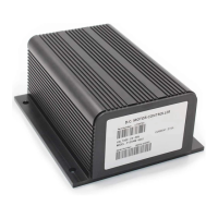
MOUNTING THE CONTROLLER
The controller can be oriented in any position, but the location should be
carefully chosen to keep the controller as clean and dry as possible. If a clean,
dry mounting location cannot be found, a cover must be used to shield the
controller from water and contaminants.
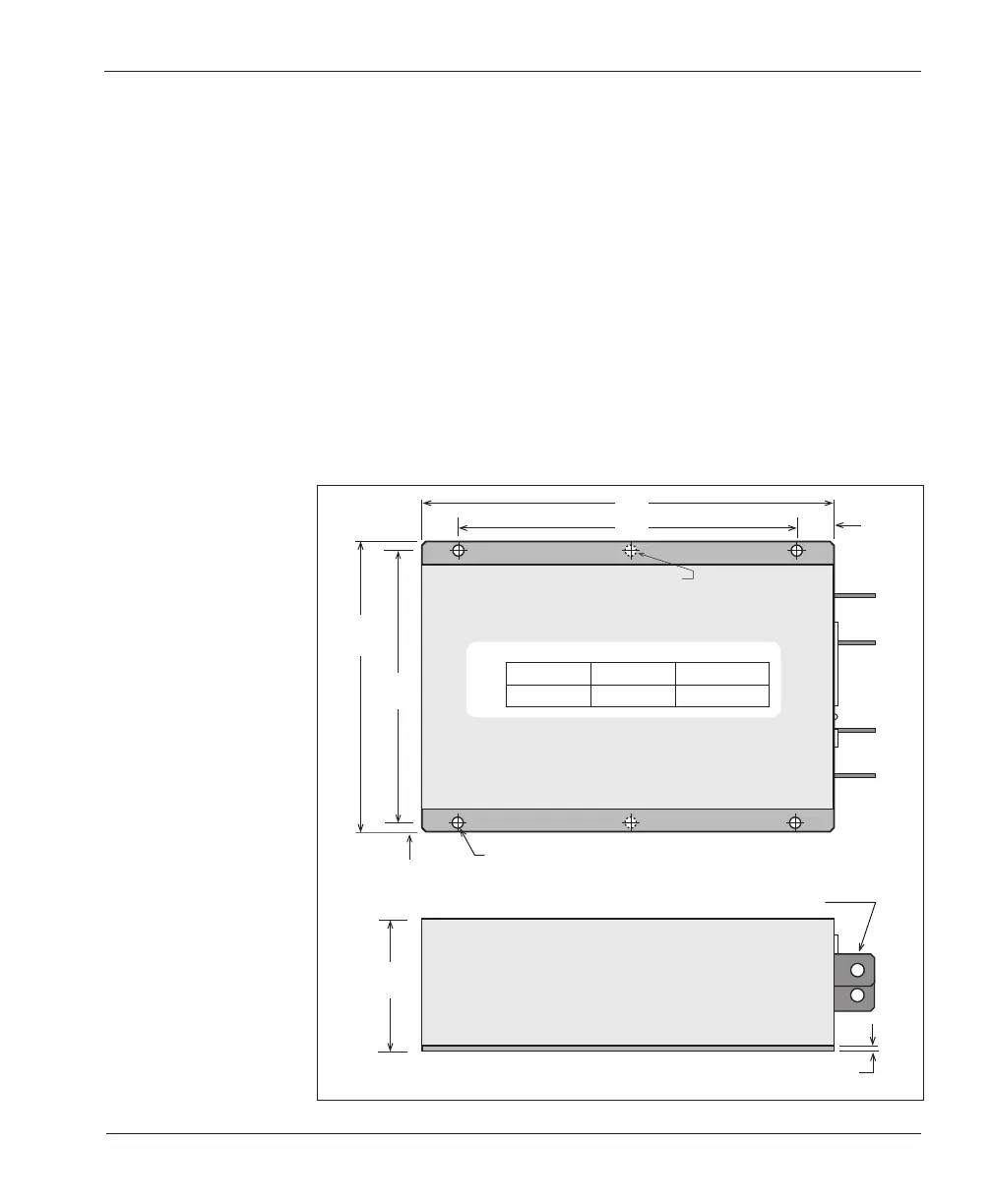
To ensure full rated output power, the controller should be fastened to a
clean, flat metal surface with four screws. The case outline and mounting hole
dimensions are shown in Figure 2. Access is needed at the front of the controller
to plug the programmer into its connector, and to view the LED.
Although not usually necessary, a thermal joint compound can be used to
improve heat conduction from the case to the mounting surface.
2
2 — INSTALLATION & WIRING
Fig. 2 Mounting
dimensions,
Curtis 1214-/15-/19-8
controllers.
169
(6.66)
5
.5
(0
.22
)
180
(7.1)
23
(0.893)
81.3
(3.2)
3.18 (0.125)
26.4
×
20.6
×
2.3 (1.04
×
0.81
×
0.09);
8.4 (0.33) dia. hole thru
7.1 (0.28) dia., 4 plcs
[6 plcs in 1219]
Dimensions in millimeters and (inches)
“B”
“A”
1214 1215 1219
“A”
210 (8.275) 253 (9.975) 309 (12.180)
“B”
165 (6.490) 208 (8.190) 264 (10.394)
[1219 MODELS ONLY]