Curtis 1214-/15-/19-8 Manual 6
WIRING: Standard Configuration
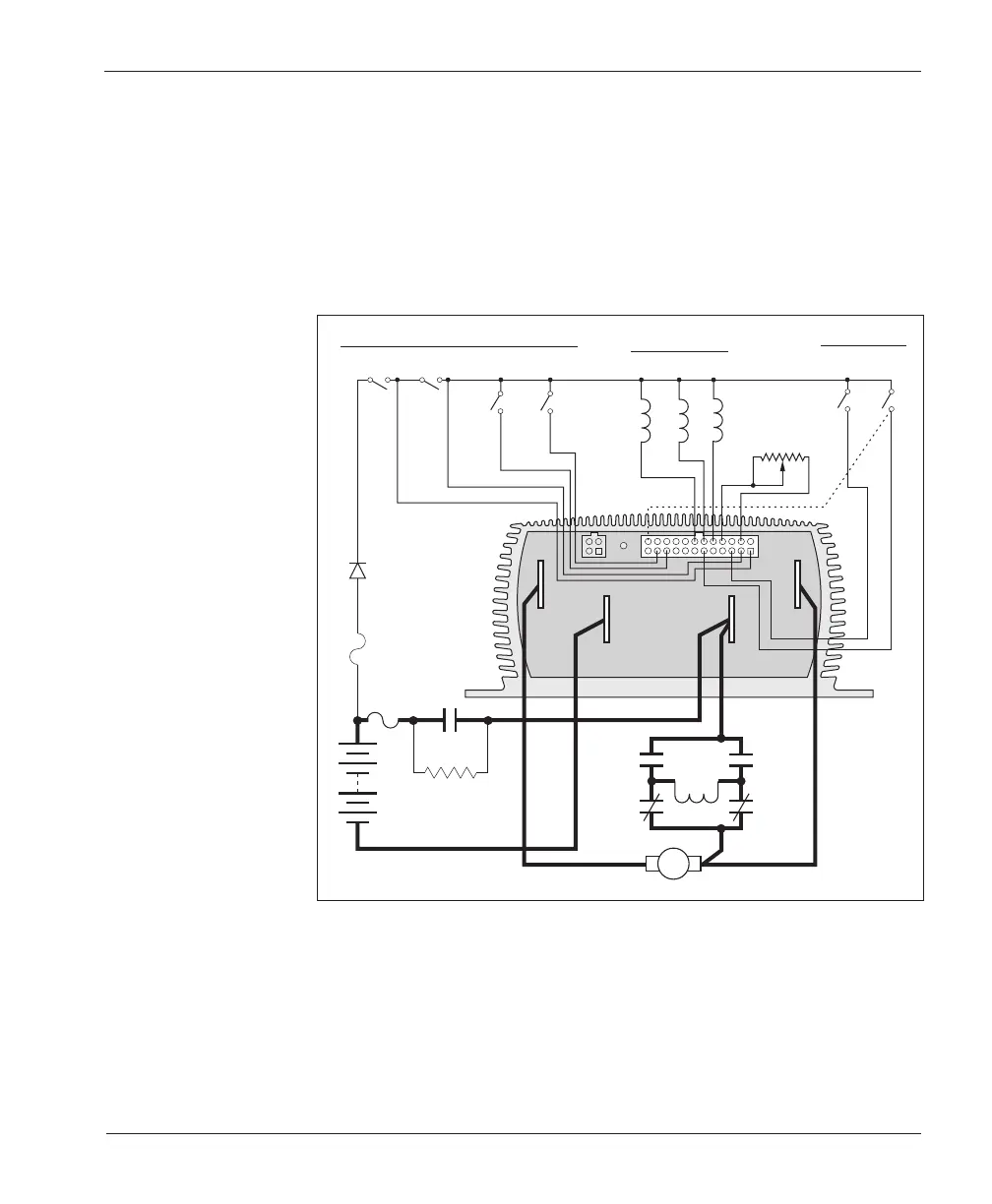
The configuration shown in Figure 3 is a typical arrangement for most applica-
tions. For walkie applications, the brake switch is typically activated by the tiller,
and a belly button switch provides emergency reverse. The emergency reverse
check feature (wiring shown by dotted line) is a factory option.
For rider applications, the brake switch is typically a seat switch or a foot
switch, and there is no emergency reverse.
2 — INSTALLATION & WIRING
Fig. 3 Standard
wiring diagram,
Curtis 1214-/15-/19-8
controller.
A
BRAKE/
SEAT
MODE
SELECT
EMERG.
REV
FORWARD
REVERSE
REV
CONTACTORS
MAIN
FWD
B-
B+
POWER
FUSE
KEYSWITCH
CONTROL
FUSE
POLARITY
PROTECTION
DIODE
5kΩ–0
THROTTLE
(TYPICAL)
MAIN
CONTACTOR
REVERSE
CONTACTOR
FORWARD
CONTACTOR
A1
A2
M-
A2
B-
B+
SWITCHES
SWITCHES
S1S2
PRECHARGE RESISTOR
(250 Ω, 5 W)
B-B-