14
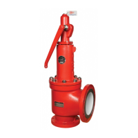
Figure 6.4
Stem Retainer
Sleeve Guide
Stem
Disc Holder
4. Remove the Blow Down Ring Lock Screw assembly [12,13, 25] and Lock
Screw Gasket [24]. Record the position of the Blow Down Ring [7] with
respect to the Disc Holder [6] by counting the number of notches required to
raise the ring until it just touches the Disc Holder [6]. This information will be
needed again when reassembling the valve. (Figure 6.3)
5. Remove the Body Hex Nuts [19]
6. Record the position of the bonnet drain relative to the valve outlet and
remove the Bonnet [2].
a. On larger valves, the combination of bonnet weight and the height that it
must be lifted to clear the Stem [9] requires that a hoist be used to remove
the Bonnet [2]. During this operation, the valve Body [1] should be
secured to prevent it from tipping over once the Bonnet [2] is removed.
b. Use care when lifting the Bonnet [2] as the Spring [20] and Stem [9]
will be able to tip over.
7. Remove the spring assembly (Spring [20] and Spring Buttons [17])
from the Stem [9]. The spring assembly must be kept together. The
Spring Buttons [17] should be tagged for later identification as the
upper and lower buttons may not be identical.
8. Using the Stem [9] as a handle, lift the complete internal assembly
from the valve Body [1]. (Figure 6.4)
a. On larger valves a hoist is advisable due to the weight of the
internal assembly.
b. An eye bolt may be attached to the stem test washer thread at the
end of the Stem [9] to assist in lifting.
c. For balanced bellows valves, use care not to damage the
bellows assembly.
d. If parts are difficult to remove due to the presence of corrosive or
foreign material soaking in a suitable solvent may be required.
9. Remove the Body Gasket [22] and Bonnet Gasket [23].
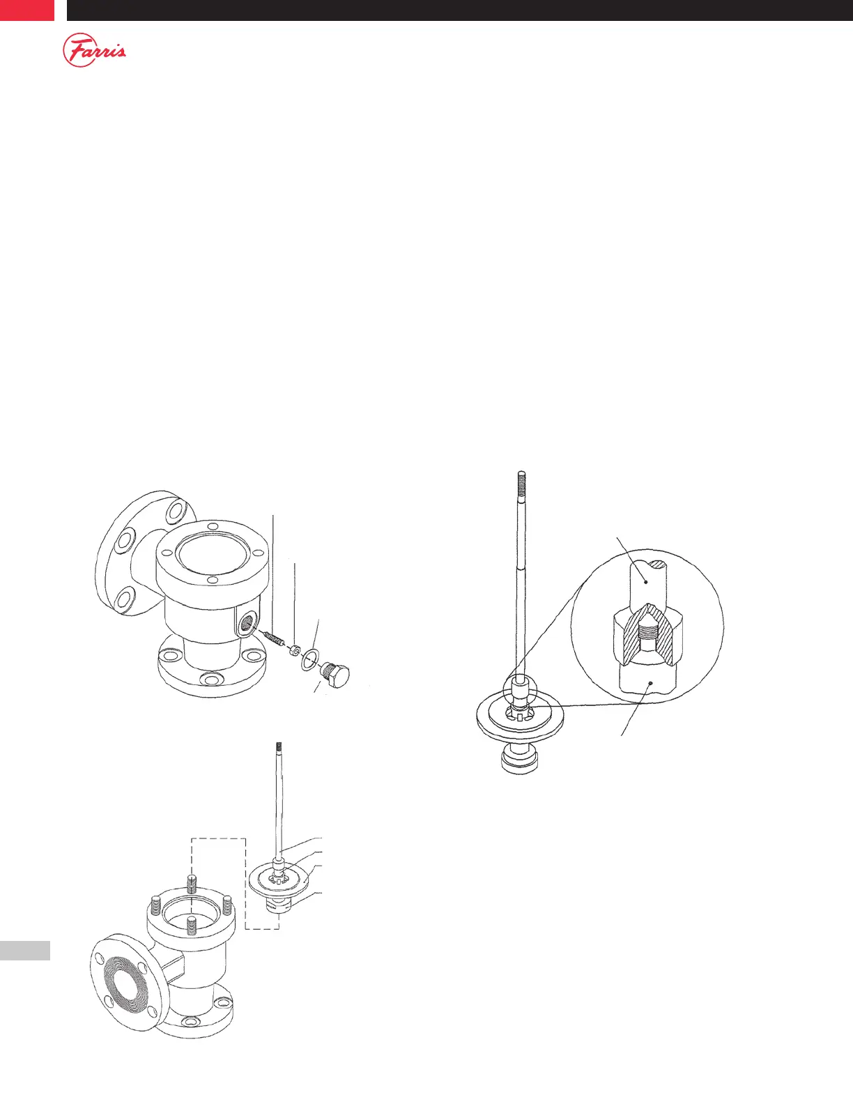
10. To remove the Stem [9] from the Stem Retainer [14], lift up on the
Stem [9] while holding the Stem Retainer [14] down and rotate
counter-clockwise at the same time. This will engage the thread.
Continue rotating until the Stem [9] is removed. (Figure 6.5)
Figure 6.3
Lock Screw Stud
Hex Nut
(B.D.R.L.S.)
Lock Screw
Gasket
Lock Screw
(B.D.R.)
Figure 6.5
Stem
Stem Retainer