15
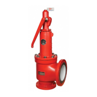
Figure 6.6
Stem Retainer
Disc
Disc Holder
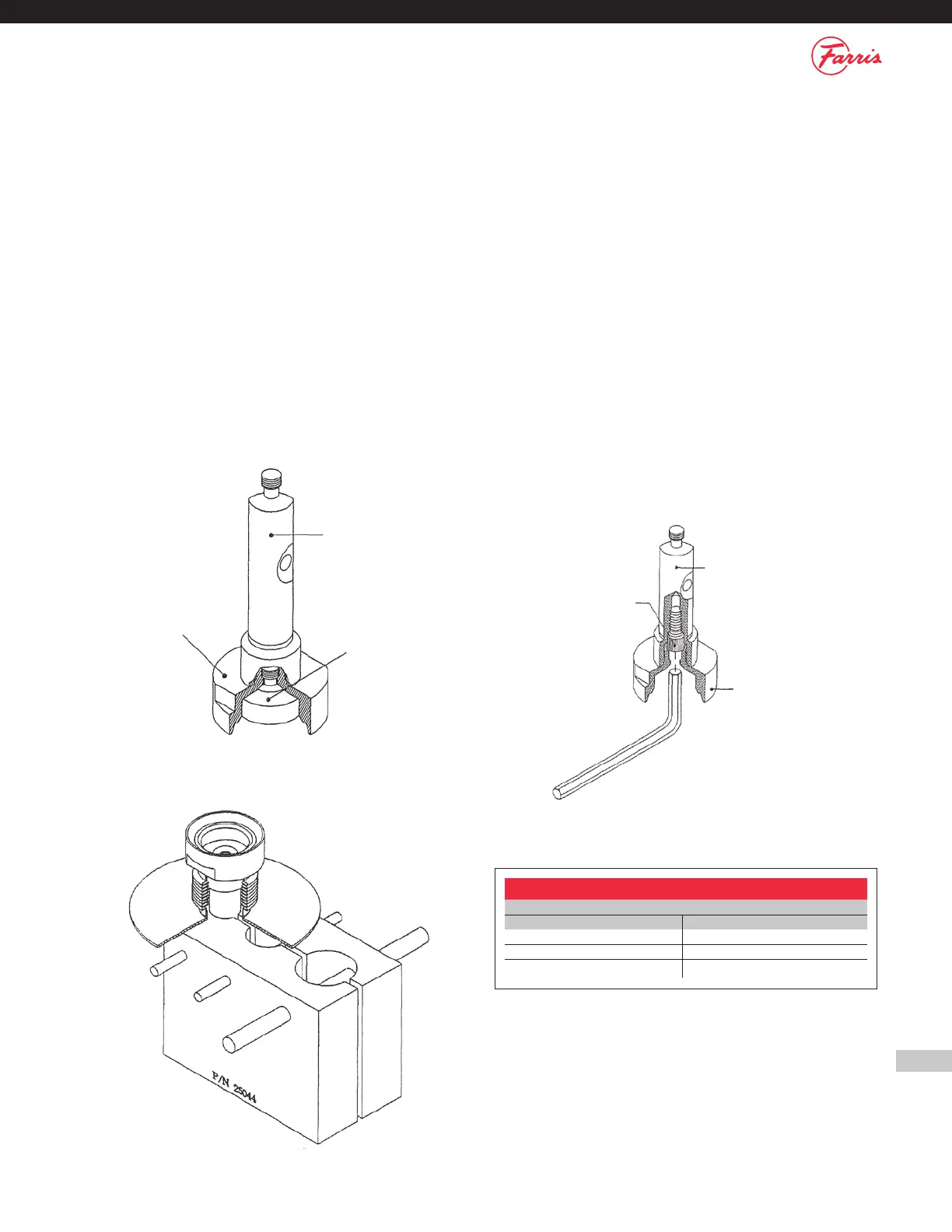
Figure 6.8
Stem Retainer
Disc Holder
Lock Screw
11. Remove the Disc [4] from the Disc Holder [6] (Figure 6.6).
a. Hold the assembly and rotate the Disc [4] with the tip of your finger.
b. For o-ring seat type valves, refer to Appendix C for instructions.
12. To separate the Disc Holder [6] from the Stem Retainer [14], first
thread the lock screw up into the Stem Retainer [14] using the fixture
shown in Figure 6.7 to hold the assembly.
a. Except for the D & E orifice bellows (A11) designs which have a one
piece stem retainer/disc holder, the Stem Retainer [14] and Disc
Holder [6] are held together with a Disc Holder Lock Screw [26].
b. The Disc Holder Lock Screw [26] has a hex socket requiring the
use of an Allen key (Figure 6.8).
c. Locking tension is relieved by threading the lock screw UP INTO the
Stem Retainer [14].
d. Allen key wrench sizes are shown in Table 6.1.
e. Be careful not to damage the guiding surface of the
Stem Retainer [14] during disassembly.
f. For bellows valves see Appendix B.
13. Remove the Blow Down Ring [7] from the Nozzle [5].
14. Turn the valve Body [1] over and re-clamp to the work bench. With a
spanner wrench and mallet, remove the Nozzle [5] from the Body [1]
a. Some valves may use wrenching flats instead of spanner holes.
NOTES:
1. For BalanSeal Bellows construction, please see Appendix B for
disassembly instructions.
2. For O-Ring seat construction, please see Appendix C for disassembly
instructions.
3. For open lever, packed lever and bolted cap construction, please
see Appendix D for disassembly Instructions.
Allen Key Sizes
Disc Holder Lock Screw
Orifices Allen Key Size
D thru J 3/16"
K thru P 7/32"
Q thru T 3/8"
Figure 6.7
Table 6.1