11.2 Calibration
The sensor calibration occurs automatically and consists in adjusting the quantity of light emitted to match the degree of
whiteness of the paper used and the degree of black of the mark printed on paper.
The device automatically performs the self-calibration during the setup procedure only if the “Notch/B.Mark Position” pa-
rameter is set to a value other than “Disabled” (see chapter 6).
Otherwise, the self-calibration can be started manually by pressing the S1 key during power-up.
When self-calibration starts, the device performs some paper feeds and then it prints the calibration result and the value
of the PWM duty-cicle of the alignment sensor driver so that it can be perform an optimal notch detection:
Autosetting Notch : OK
PWM Duty Cycle : 85.3%
The “Autosetting Notch” parameter indicates the result of the self-calibration procedure; OK will appear if it has been suc-
cessful, NOT OK will appear if the procedure has failed.
After the printing of the procedure result, the device offers the execution of the function of paper characterization “Characterize
Paper” and the change of the “Notch/B.Mark Threshold” parameter which represents the detection threshold of the notch.
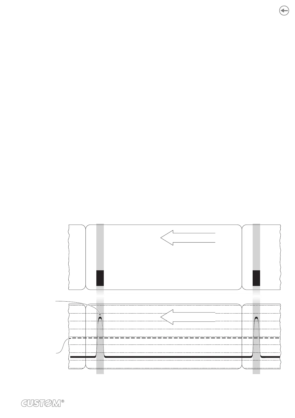
Choosing the “Yes” value for the “Characterize Paper” parameter, the device prints a graphic representation (see following
This graphic representation is useful to set the most suitable value to assign to the “Notch/B.Mark Threshold” parameter
and then to better identify the optimal threshold value which takes into account the variations of the signal and the small
oscillations around zero.
is constant while passing the white paper between two black marks and presents a peak at each black mark.
In this case, the optimal value for the “Notch/B.Mark Threshold” parameter is placed about half of the peak (as shown in
NON-THERMAL SIDE
Peak
“Notch/B.Mark
Threshold”
THERMAL SIDE
175