P/N IM-AR5 Rev. F
© 2017 Johnson Controls. All rights reserved. All specifications and other information shown were current as of document
revision date and are subject to change without notice.
23
Section 6 – RM-5 Relay Module
6.1 Description
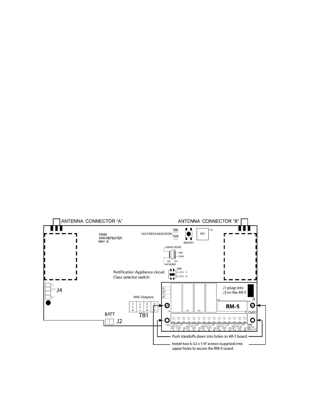
The RM-5 relay module is an optional sub assembly for adding 5 form C relay outputs directly to the
AR-5 board. The 5 relays and terminal connections are located on a pc board which plugs into the
AR-5. The outputs are then available inside of the AR-5 enclosure. The outputs are rated 30Vdc 5A.
6.2 Installation
Warning: Make sure the AR-5 repeater is powered off prior to installing the RM-5 sub
assembly. The RM-5 board is snapped into the AR-5 board with standoffs and held in position with
two supplied 6-32 machine screws. Position the RM-5 over the lower right side of the AR-5 board so
the connector J1 on the bottom of the RM-5 board is aligned with the J3 relay expansion connector
on the AR-5. Holding the RM-5 board, firmly push the nylon standoffs on the RM-5 into the two lower
holes on the AR-5 until they snap in. After seating the RM-5 board install the two 6-32 screws into the
upper two holes and tighten them. Do not over tighten. Refer to figure 8.
6.2.1 Wiring
Refer to figure 9 for wire routing. Follow all NFPA and local electrical codes when wiring this product.
Acceptable wire size is 16-22 awg. The RM-5 board is silkscreened with the connections for the
terminal block with each relay number and NC COM NO designations. The relay outputs are for
connection to power limited circuits only. Relay contacts are rated at 30Vdc 5A resistive.
6.2.2 Programming
Many programming options are available for the RM-5 relay board. Since relay activation and
deactivation is programmed at the CP-3600(+) control panel, please refer to that manual for
programming options and instructions.
Figure 8
 Loading...