3.3.2 AC Input & Output Connection
CAUTION:
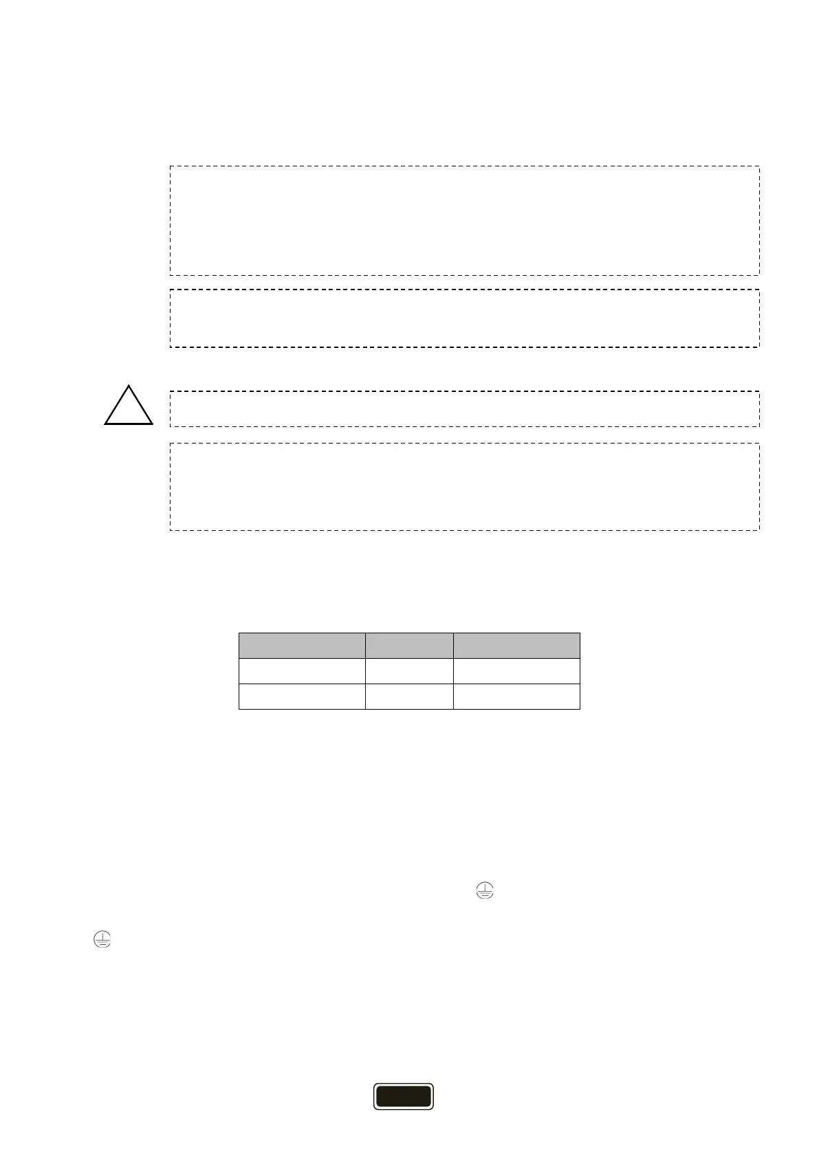
Suggested cable requirement for AC wires:
Table 3-2
Please follow below steps to implement AC input/output connection:
1. Before making AC input/output connection, be sure to open DC protector or disconnector first.
2. Remove insulation sleeve 10mm for six conductors. And shorten phase L and neutral conductor
N 3mm.
3. Insert AC input wires according to polarities indicated on terminal block and tighten the terminal
screws. Be sure to connect PE protective conductor ( ) first.
→ Ground (yellow-green)
L → LINE (brown)
N → Neutral (blue)
Model Wire size Torque value
CPS5000ECH48 1*8AWG 1.4-1.6Nm
CPS3000ECH48 1*10AWG 1.4-1.6Nm
Before connecting to AC input power source, please install a separate
between inverter and AC input power source. This will ensure the inverter can be
securely disconnected during maintenance and fully protected from over current of
AC input. The recommended spec of AC breaker is 50A for 5KVA.
There are two terminal blocks with “IN” and “OUT” markings. Please do NOT
mis-connect input and output connectors.
All wiring must be performed by qualified personnel.
It's very important for system safety and efficient operation to use appropriate cable
for AC input connection. To reduce risk of injury, please use the proper recommended
cable size as below.