3
CP1500EPFCLCD,). If the rated unit capacities are exceeded, an overload condition may occur and
cause the UPS unit to shut down or the circuit breaker to trip.
BASIC OPERATION
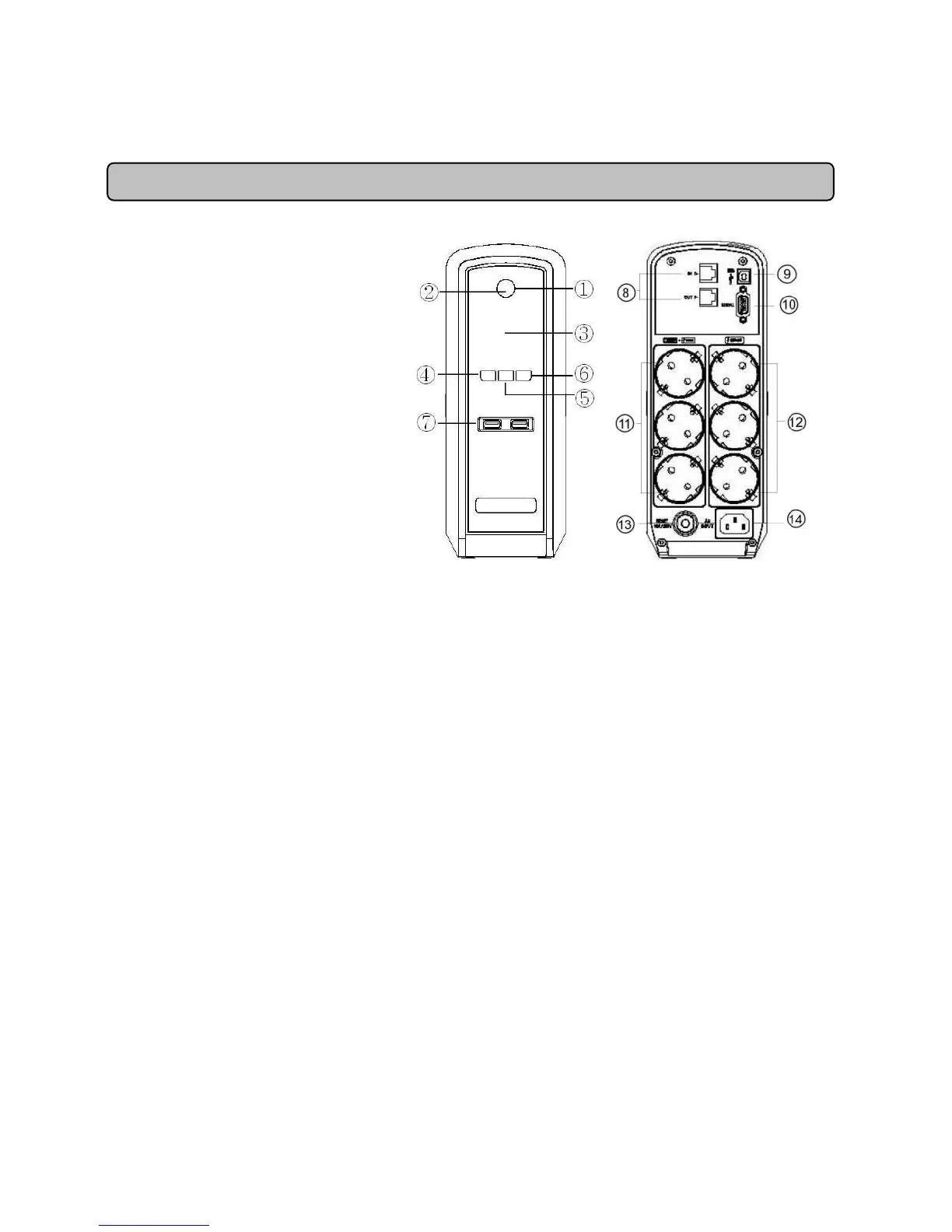
DESCRIPTION
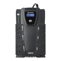
1. Power Switch
Used as the master on/off switch
for equipment connected to the
battery power supplied outlets.
2. Power On Indicator
This LED is illuminated when the
utility power is normal and the UPS
outlets are providing power, free of
surges and spikes.
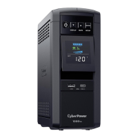
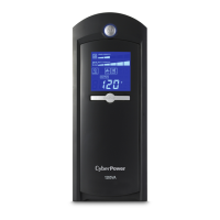
3. LCD Module Display
High resolution and intelligent LCD
display shows all the UPS
information with icons and
messages. For more information
please check the “Definitions for Illuminated LCD Indicators” section.
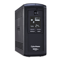
4. Display Switch
The switch can be used to select the LCD display contents including Input Voltage, Output Voltage
and Estimated Run Time. The toggle frequency is set to one time per 0.5 second. Press the switch
to roll down the function menu. Pressing the switch for 2 seconds will turn the LCD display on or off
while in AC/Utility power mode.
5. Silence Alarm Switch
The toggle frequency is set to one time per 0.5 second. Press the switch to roll up the function
menu. Holding the switch for more than 2 seconds will silence the buzzer.
6. Control Switch
Press the Control switch for 3 seconds in AC/Utility Power Mode to perform a Self Test of the
battery.
7. USB Power Ports
The USB Power ports provide 5V 1A power output.
8. Communication Protection Ports RJ11/RJ45
Communication protection ports will protect any standard modem, fax, telephone line, or network
cable from surge and spikes.
9. USB Port to PC
This port allows connection and communication from the USB port on the computer to the
UPS unit. The UPS communicates its status to the PowerPanel
®
Personal Edition software.
10. Serial Port to PC
This port allows connection and communicates from the DB-9 serial on the computer to the
UPS unit. The UPS communicates its status to the PowerPanel
®
Personal Edition software.
NOTE: Only one of these two ports can be used as communication and control of the UPS unit at
one time.
11. Battery and Surge Protected Outlets