Copyright © 2017 Cyber Power Systems, Inc.
BACKFEED PROTECTION OPERATION
1. If the Bypass circuit is shorted and the UPS is running in Line Mode or Battery Mode, backfeed protection will be active and the external isolation device
(Magnetic Contactor) will open.
2. Save your data and perform a controlled shutdown.
3. Contact CyberPower for repair.
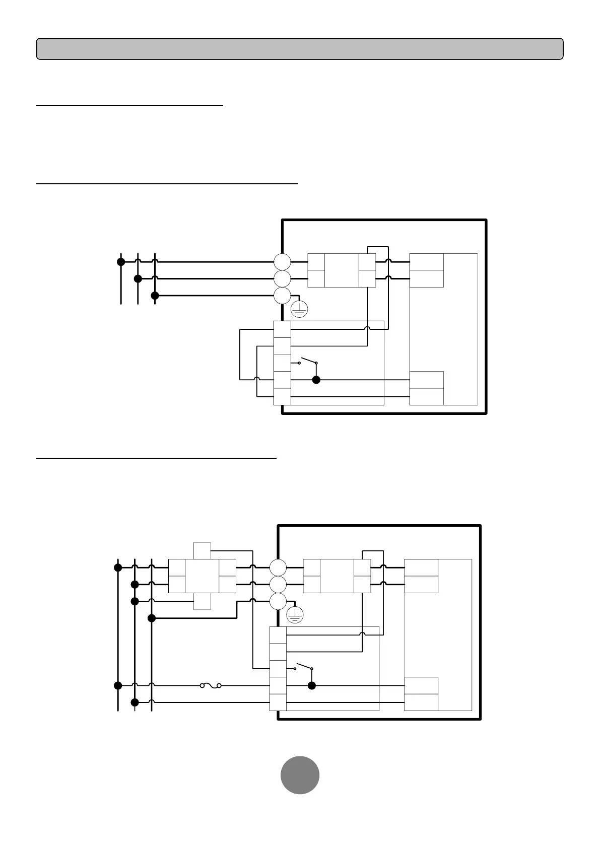
WITHOUT BACKFEED PROTECTION CONFIGURATION
1. Hardwire the input terminals as shown in the following diagram.
2. Do not remove the interconnection wires (Jumper1 / Jumper2) on “Backfeed Protection Connector”.
UPS
L1
L2
PSDR
AC-L1
AC-L2
IP-L1
IP-L2
Backfeed
1
2
4
5
3
L1
L2
I/P
EMI
L1
L2
L1 L2 PE
Mains
PE
Jumper2
Jumper1
WITH BACKFEED PROTECTION CONFIGURATION
1. Customers should provide an external isolation device (Magnetic Contactor) which is upstream and outside the UPS and capable of supporting the UPS
input current.
2. Remove the interconnection wires (Jumper1 / Jumper2) on “Backfeed Protection Connector”.
3. Hardwire the input terminals and “Backfeed Protection Connector” as shown in the following diagram.
4. The external isolation device must be installed in the Mains path.
UPS
L1
L2
PSDR
AC-L1
AC-L2
IP-L1
IP-L2
Backfeed
1
2
3
4
5
MC
L1
L2
L1
L2
A1
A2
I/P
EMI
L1
L2
L1
L2
L1 L2 PE
Mains
PE
2A Fuse
(Slow Blow)
 Loading...