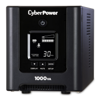
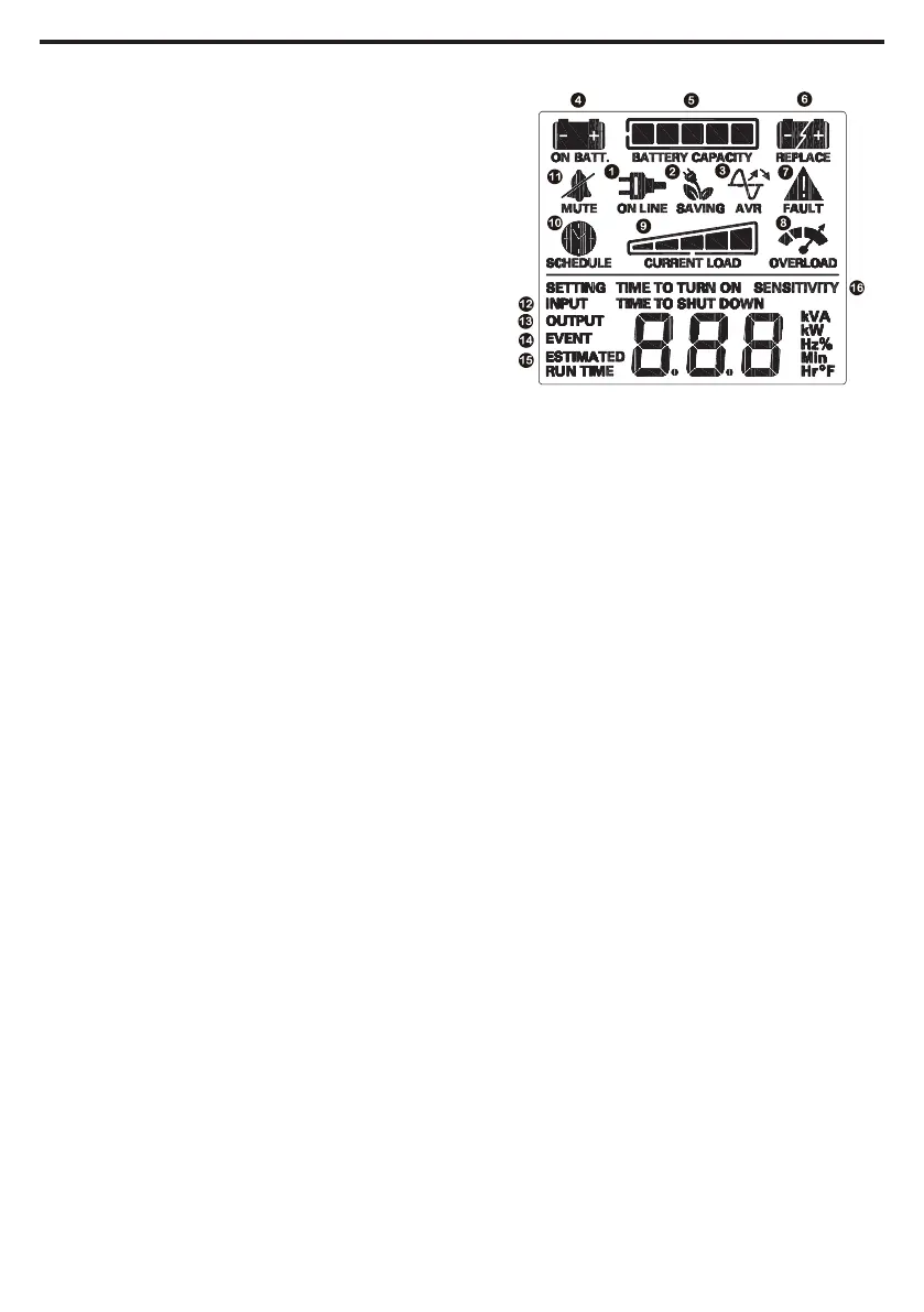
DEFINITIONS FOR ILLUMINATED LCD INDICATORS
1. ONLINE:
The UPS is supplying utility power to
connected equipment.
2. ENERGY-SAVING:
The UPS is in energy saving bypass mode.
See “CYBERPOWER GREENPOWER UPS™
TECHNOLOGY” section for more information.
3. AVR (Automatic Voltage Regulation):
This icon appears whenever your UPS is
automatically correcting low or high AC line
voltage without using battery power. This is
a normal, automatic operation of your UPS,
and no action is required on your part.
4. ON BATTERY:
During a severe sag or loss in utility power,
this icon appears and an alarm sounds
(two short beeps followed by a pause) to
indicate the UPS is operating from its inter-
nal batteries. During a prolonged sag or loss
in utility power, the alarm will beep rapid-
ly every 1/2 second to indicate the UPS’s
batteries are nearly out of power. You should
save files and turn o your equipment im-
mediately or allow the software to shut the
system down.
5. BATTERY CAPACITY:
This meter displays the approximate
charge level (in 20% increments) of the
UPS’s internal battery. During a severe sag
or loss in utility power, the UPS switches
to battery power, the ON BATTERY icon
appears, and the charge level decreases.
6. REPLACE battery:
This icon illuminates when the batteries
are not connected well or the batteries
were worn out.
7. FAULT: This icon appears if there is a
problem with the UPS. Press the POWER
button to turn the UPS o.
E01: Charger Fault – Overcharge
(Contact CyberPower Systems for support.)
E02: Charger Fault – No Charge
(Contact CyberPower Systems for support.)
E11: Battery Overvoltage
(Contact CyberPower Systems for support.)
E21: Battery Output Short Fault
(Turn on the UPS)
E22: Battery Mode or AC/Utility Power
Mode Overload Fault (Unplug at least one
piece of equipment from battery outlets
and turn the UPS on again.)
8. OVERLOAD:
This icon appears and an alarm sounds
to indicate the battery-supplied outlets
are overloaded. To clear the overload,
unplug one piece of equipment from the
battery-supplied outlets at a time until the
icon turns o and the alarm stops.
9. CURRENT LOAD:
This meter displays the approximate
output load level (in 20% increments)
of the UPS battery outlets.
10. SCHEDULE:
Users can setup the schedule to turn on and
shut down the computer and UPS through
PowerPanel® software. The LCD display will
show how much time is left before the UPS
will turn back on or shut down.
11. MUTE:
This icon appears whenever the UPS is
in silent mode. However, when there is a
problem with the UPS, the alarm will still
beep even in silent mode.
12. INPUT Meter:
This meter measures the AC voltage that
the UPS system is receiving from the utility
wall outlet. The UPS is designed, through
the use of automatic voltage regulation,
to continuously correct output voltage to
connected equipment to a safe 110/120
voltage output range. In the event of
a complete power loss, severe sag, or
over-voltage, the UPS relies on its inter-
nal battery to supply consistent 110/120
output voltage. The INPUT voltage meter
can be used as a diagnostic tool to identify
poor-quality input power.
 Loading...