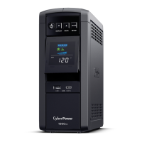
BASIC OPERATION
1.
P
ower Switch
Used as the mast
er on/o switch for
equipment connected t
o the battery power
supplied outlets.
2.
Pow
er On Indicator
This LED is illuminated when the utility
power is normal and the UPS outlets ar
e
providing power, free of surges and spikes.
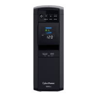
3.
LCD Module Display
High resolution and intelligent LCD display
shows all the UPS inf
ormation using icons
and messages. For more information please
revie
w the “Definitions for Illuminated LCD
Indicators” section below.
4. Display Switch
The switch can be used to select the LCD
display contents including Input Voltage,
Output Voltage, and Estimated Run Time.
T
he toggle frequency is set to one time per
0.5 second. Press the switch to roll down
the function menu. Pressing the switch for
2 seconds will turn the LCD display on or
o while in AC/Utility power mode.
5. Silence Alarm Switch
The toggle frequency is set to one time per
0.5 second. Press the s
witch to roll up the
function menu. Holding the switch for more
than 2 seconds while running on battery
will silenc
e the buzzer.
6 Control Switch
Press the Control switch for 3 seconds in
AC/Utility Power Mode t
o perform a Self
Test of the battery.
7. USB Charging Ports
The USB charging ports provide DC 5V 2.1A
power output.
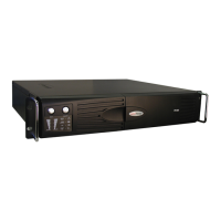
8. Batt
ery and Surge Protected Outlets
The unit has five battery powered/
surge suppression outlets for c
onnected
equipment to ensure temporary
uninterrupted operation of your equipment
during a power failure. (DO NOT plug a
laser printer, paper shredder, copier, space
heater, vacuum, sump pump or other
large electrical devices into the “Battery
and Surge Protected Outlets”. The power
demands of these devices may overload
and damage the unit.)
9. Full-Time Surge Protection Outlets
The unit has five surge suppression outlets.
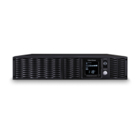
10. Circuit Breaker
L
ocated on the back of the UPS, the circuit
breaker provides o
verload and fault protection.
11. Serial/USB Port to PC
The USB communication port allows
communication between the USB port
on the comput
er and the UPS unit.
12. Communication Protection Ports (RJ45)
Communication protection ports,
bi-directional, will protect a 10/
100/1000
Ethernet connection(RJ45).
13. Wiring Fault Indicator (red)
This LED indicator will illuminate to warn
the user that a wiring problem exists, such
as bad gr
ound, missing ground or reversed
wiring. If this is illuminat
ed, disconnect all
electrical equipment from the outlet and
have an electrician verify the outlet is
properly wired. The unit will not provide
surge protection without being plugged
into a grounded and properly wired wall
outlet.
14. Coax/Cable/DSS Surge Protection
The Coax/Cable/DSS protection ports will
protect any cable modem, CATV c
onverter,
or DSS receiver..
14. Outlets Designed for AC Adapters
The unit has two outlets spaced to allow
AC power adapter blocks t
o be plugged
into the UPS without blocking adjacent
outlets.
 Loading...