Installation
1. Open the display lock clip, set the display in the left handlebar (standard handlebar sizeΦ22.2). Adjust it
in place and tighten the screw accordingly.
Note: Damage caused by excessive torque is not covered by the warranty.
Certication
CE / IP65 (waterproof) / ROHS.
Be sure to contact techinical_support@cycmotor.com if further assitance is needed. Thank you!
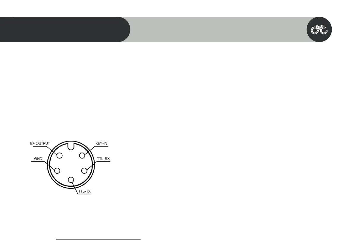
1. Red wire: Anode (36V to 72V)
2. Black wire: GND
3. Yellow wire: TxD (display -> controller)
4. Green wire: RxD (controller -> display)
5. Blue wire: Power cord to the controller
Pin Layout
37
SW102 DISPLAY GUIDE
05
Male 5-Pin Connector