75D-Link DCS-5222LB1 User Manual
Appendix A: DI/DO Specications
DI/DO Specications
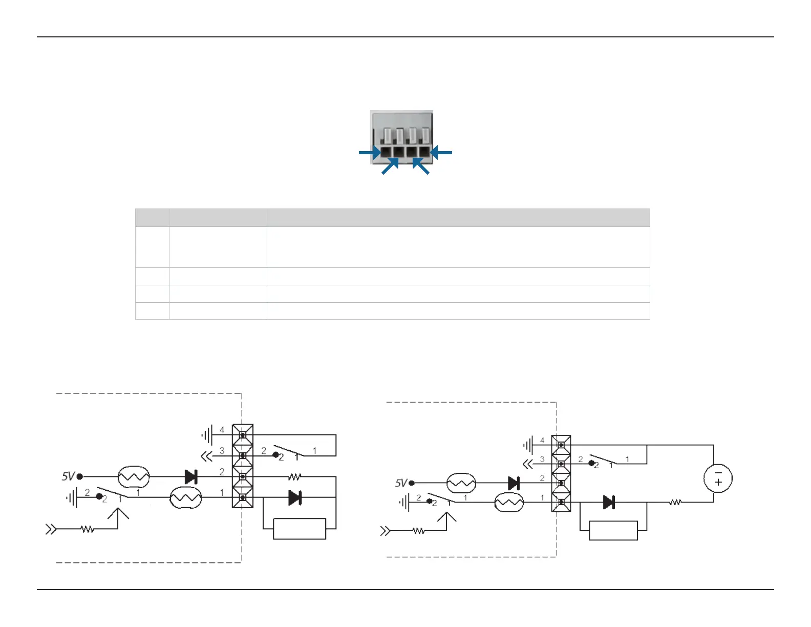
Pin 1 Pin 4
Pin 3Pin 2
Internal 5V Power External 3~12V Power
DI Input
DO Output
GPIO
PTC 1
PTC 2
DI Input
DO Output
GPIO
PTC 1
PTC 2
DC3 V ~ 12V
PIN FUNCTION
NOTE
1 Digital Out (DO) Uses an open-drain NFET transistor with the source connected to GND in camera. If used
with an external relay, a diode must be connected in parallel with the load for protec-
tion against voltage transients. Max loading is 100 mA.
2 DC5V OUTPUT DC 5 V Output / Max. 100 mA
3 Digital In (DI) A switch from DI to GND, activated by setting NO. or NC.
4 GND GND