DES-3226S Layer 2 Fast Ethernet Switch User’s Guide
6
3
Identifying External Components
This chapter describes the front panel, rear panel, optional plug-in modules, and LED indicators of the DES-3226S.
Front Panel
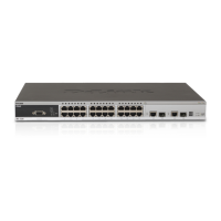
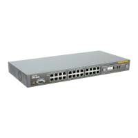
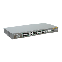
The front panel of the Switch consists of LED indicators, an RS-232 communication port, a slide-in module slot, and 24
(10/100 Mbps) Ethernet/Fast Ethernet ports.
Figure 3 - 1. Front panel view of the Switch
• Comprehensive LED indicators display the status of the Switch and the network (see the LED Indicators section below).
• An RS-232 DCE console port for setting up and managing the Switch via a connection to a console terminal or PC using a
terminal emulation program.
• A front-panel slide-in module slot for Gigabit Ethernet ports can accommodate a 2-port 1000BASE-T Gigabit Ethernet
module, a 2-port 1000BASE-SX Gigabit Ethernet module, a 2-port 1000BASE-LX Gigabit Ethernet module, or a 2-port
GBIC-based Gigabit Ethernet module.
• Twenty-four high-performance, NWay Ethernet ports all of which operate at 10/100 Mbps with Auto-MDIX function for
connections to end stations, servers and hubs. All ports can auto-negotiate between 10Mbps or 100Mbps, full or half
duplex, and flow control.
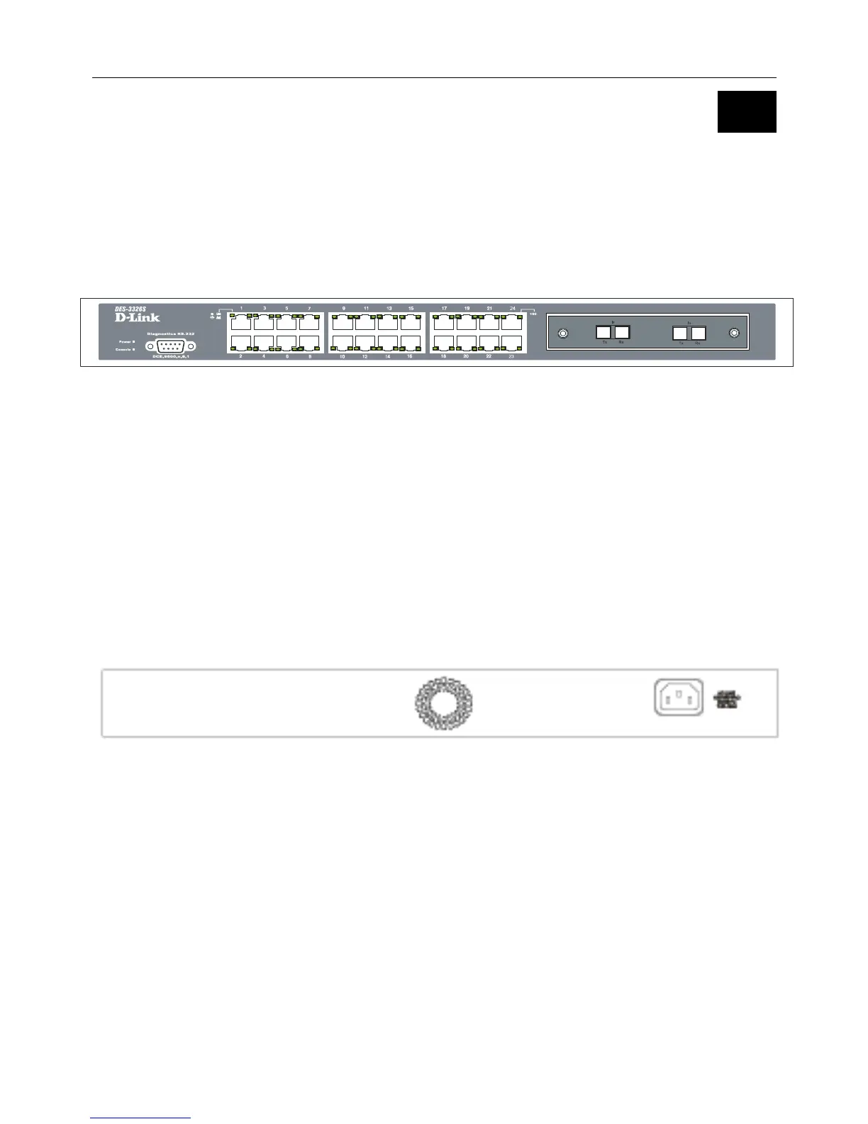
Rear Panel
The rear panel of the Switch contains an AC power connector.
Figure 3 - 2. Rear panel view of the Switch
The AC power connector is a standard three-pronged connector that supports the power cord. Plug-in the female connector of
the provided power cord into this socket, and the male side of the cord into a power outlet. Supported input voltages range
from 100 ~ 240 VAC at 50 ~ 60 Hz.