DES-3226S Layer 2 Fast Ethernet Switch User’s Guide
15
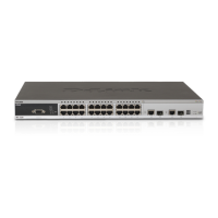
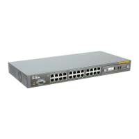
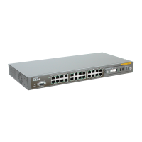
DES-332GS 1-port GBIC-Based Gigabit Ethernet Switch and stacking Module
Figure 3 - 11. Stacking Module with one GBIC port
Port Functions
• 1 GBIC-Based Gigabit Ethernet port
• Allows multi-mode fiber optic connections of up to 550 m (SX and LX) and single-mode fiber optic connections of
up to 5 km (LX only). GBIC modules are available in –SX and –LX fiber optic media.
• IEEE 802.3z 1000BASE-SX compliance
• Supports Full-duplex operations
• IEEE 802.3x compliant Flow Control support for full-duplex
Stacking Port Function
• 1 transmitting port and 1 receiving port
• IEEE1394.b compliance
• Forwarding rate up to 965Mbps
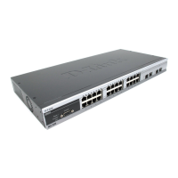
DEM-320GS 1-port GBIC-Based Gigabit Ethernet Switch and stacking Module
Port Functions
• 1 GBIC-Based Gigabit Ethernet port
• Allows multi-mode fiber optic connections of up to 550 m (SX and LX) and single-mode fiber optic connections of
up to 5 km (LX only). GBIC modules are available in –SX and –LX fiber optic media.
• IEEE 802.3z 1000BASE-SX compliance
• Supports Full-duplex operations
• IEEE 802.3x compliant Flow Control support for full-duplex
Stacking Port Function
• 1 transmitting port and 1 receiving port
• IEEE1394.b compliance
• Forwarding rate up to 965Mbps
LED Indicators
Link
Off – No Link
Solid Green – Link
Active
Off – No Activity
Blinking Green – Activity
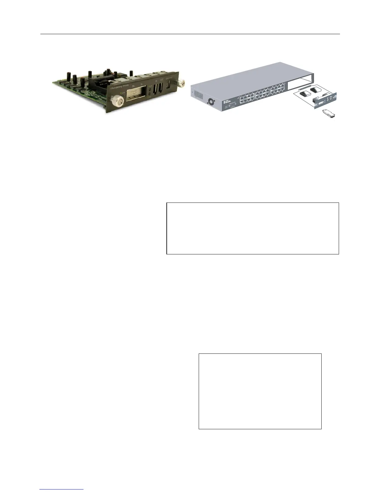
The optional Stacking Module allows up to eigh
Switch’s serial port (via the management station’s
console and the Switch’s Command Line Interface).
The stacking module’s LED indicators are describe
 Loading...