DGS-1520 Series Gigabit Ethernet Smart Managed Switch Hardware Installation Guide
2
2. Hardware Components
Front Panel Components
Rear Panel Components
Side Panel Components
Front Panel Components
The front panel features components like LED indicators, a reset button, a Console port, and a variety of Ethernet
ports. These components are described in detail below.
This following table lists the front panel components on all the switches in the series:
Port Description
Reset Button
The reset button is used to reboot the switch or to reset the switch to its factory
default settings depending on how long this button is pressed.
• Press and hold for less than 5 seconds - This reboots the Switch. All
unsaved configurations will be lost.
• Press and hold for between 5 and 10 seconds - This reboots the Switch
and restarts the ZTP function. All unsaved configurations will be lost.
• Press and hold for more than 10 seconds - This resets the software
configuration on the Switch to the factory default settings.
Console Port
The console port is used to connect to the CLI of the switch. The connection is out-
of-band and the console cable (included in the package) must be used for the
connection.
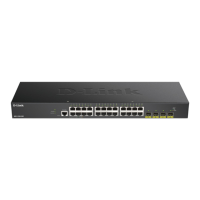
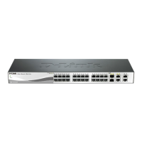
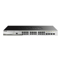
Figure 2-1 DGS-1520-28 Front Panel
This following table lists the front panel components unique to the DGS-1520-28:
Port Type Port Number Description
RJ45 Port
(10/100/1000 Mbps)
Ports 1 to 24 This switch is equipped with 24 RJ45 Ethernet ports that can
operate at 10 Mbps, 100 Mbps, and 1 Gbps wire-speeds.
RJ45 Port
(1/10 Gbps)
Ports 25 to 26 This switch is equipped with 2 RJ45 Ethernet ports that can
operate at 1 Gbps and 10 Gbps wire-speeds.
SFP+ Ports
(1/10 Gbps)
Ports 27 to 28 This switch is equipped with 2 SFP/SFP+ ports that can
operate at 1 Gbps and 10 Gbps wire-speeds and support a
wide collection of SFP/SFP+ transceivers.
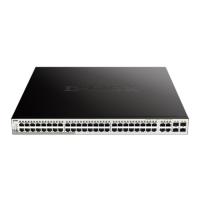
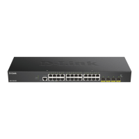
Figure 2-2 DGS-1520-28MP Front Panel
 Loading...