NOTE: The S FP c ombo p orts on t he S witch c annot be us ed s imultaneously with t he
corresponding 10 00BASE-T por ts. I f bot h por ts are in us e at t he s ame t ime, t he SFP
ports will t ake pr iority over t he c ombo por ts and r ender the 1 000BASE-
inoperable.
NOTE: For c ustomers i nterested in D -View, D -Link C orporation's pr oprietary S NMP
management s oftware, g o t o t he D -Link Website ( www.dlink.com) and d ownload t he
software and manual.
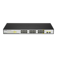
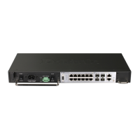
Front-Panel Components
DGS-3700-12
• Eight 10/100/1000BASE-T ports
• Four Combo 1000BASE-T/SFP ports located to the right
• One female DCE RS-232 DB-9 console port
• One 10/100Base-Tx out of band management port
• One RJ-45 alarm port
• LEDs for AC Power, DC Power, Console, Management, Fan, Master, Link/Act/Speed for each port
• Grounding post
• Fan module
• Power module consisting of the following components:
− AC power connector (power cord provided, supports voltage 100~240 VAC at 50~60 Hz 1.5A Max)
− AC power Switch
− DC power connector (supports voltage 48VDC 1.6A Max)
− DC power switch
CAUTION: The handles on the power and fan modules should only be used to replace the modules in
the event of a hardware failure. Do not use the power module handle to lift the Switch.
Figure 1- 1. Front Panel View of the DGS-3700-12 switch
 Loading...