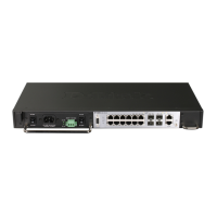
DES-3700-12G
• Eight 1000M SFP ports
• Four 10/100/1000BASE-T ports located to the right
• One female DCE RS-232 DB-9 console port
• One 10/100Base-Tx out of band management port
• One RJ-45 alarm port
• LEDs for AC Power, DC Power, Console, Management, Fan, Master, Link/Act/Speed for each port
• Grounding post
• Fan module
• Power module consisting of the following components:
− AC power connector (power cord provided, supports voltage 100~240 VAC at 50~60 Hz 1.5A Max)
− AC power Switch
− DC power connector (supports voltage 48VDC 1.6A Max)
− DC power switch
CAUTION: The handles on the power and fan modules should only be used to replace the modules in
the event of a hardware failure. Do not use the power module handle to lift the Switch.
Figure 1- 2. Front Panel View of the DGS-3700-12G switch
LED Indicators
The Switch supports LED indicators for Power, Console, Management, Fan and Port LEDs. The following shows the
LED indicators for t he D GS-3700 Series al ong with an ex planation of each indicator. LEDs and their corresponding
meanings are displayed below.
Figure 1- 3. LED Indicators on DGS-3700-12 switch
Figure 1- 4. LED Indicators on DGS-3700-12G switch
 Loading...