10/100 Fast Ethernet Switch Manual
7
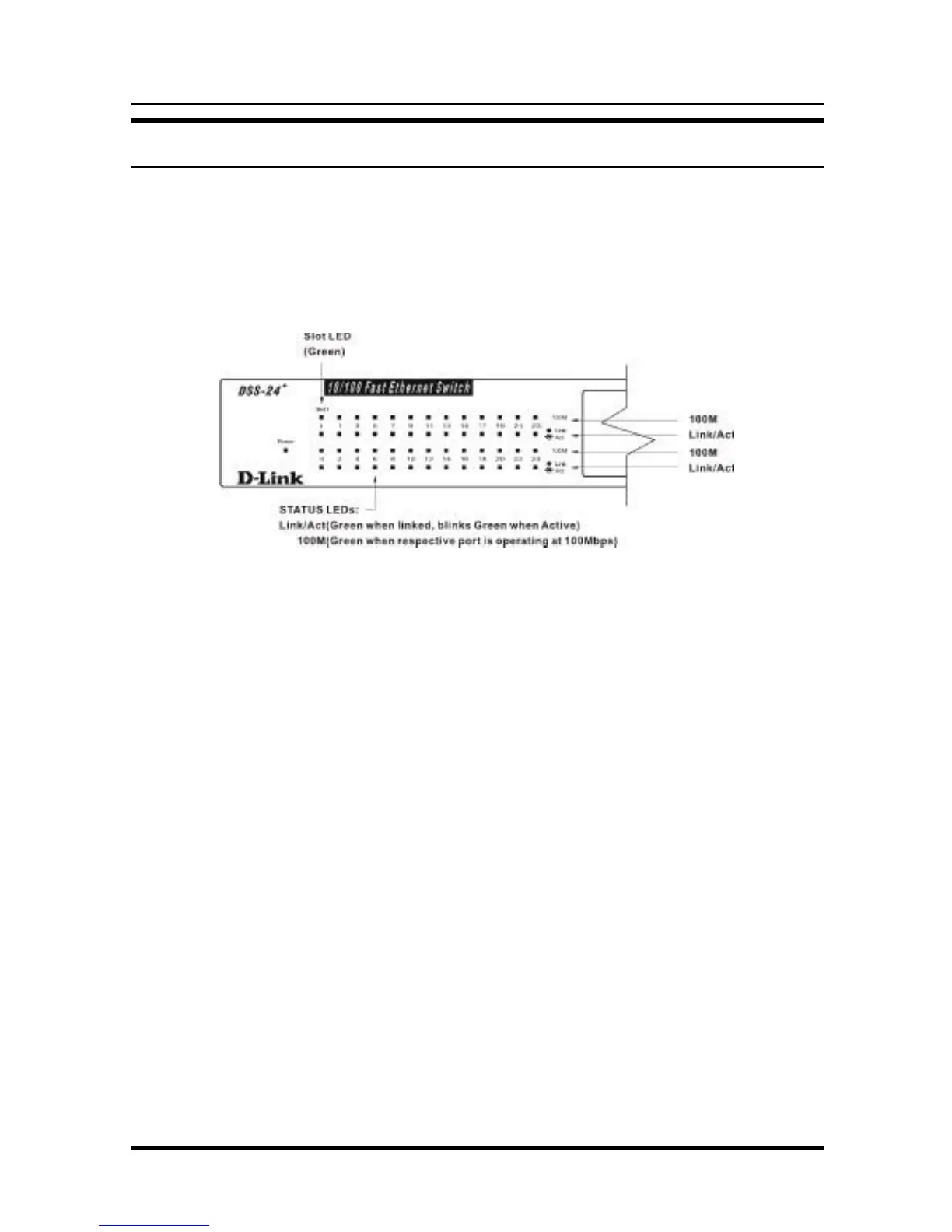
LED Indicators
The LED indicators of the Switch include Power, 100M, Link/Act
(Link/Activity), and Slot. The LED indicators are used to facilitate
monitoring and troubleshooting of the Switch. The following
shows the LED indicators for the Switch along with an
explanation of each indicator.
Figure 3.3 The DSS-24+ Switch LED indicators
♦ Power This indicator operates when the Switch is turned on.
If this indicator is not lit, check the AC power connector to
ensure proper insertion of the power cord.
♦ 100M The LED indicator lights green when a 100 Mbps
device is connected to a respective port. If a 10 Mbps device
is connected to a respective port, the LED indicator is OFF.
♦ Link/Act These LED indicators are lighted green when
there is a secure connection (or link) to a device at any of
the ports. The LED indicators blink green whenever there is
reception or transmission (i.e. Activity— Act) of data
occurring at a port.
♦ Slot This LED indicator is lighted green when there is a
secure connection (or link) to an optional two-port
100BASE-FX (SC type) module installed in the front panel.
Each port has its own LED, designated as I and II. See
100M and Link/Act indicator descriptions above for further
information.