10/100 Fast Ethernet Switch Manual
6
3
2 IDENTIFYING EXTERNAL
COMPONENTS
Front Panel
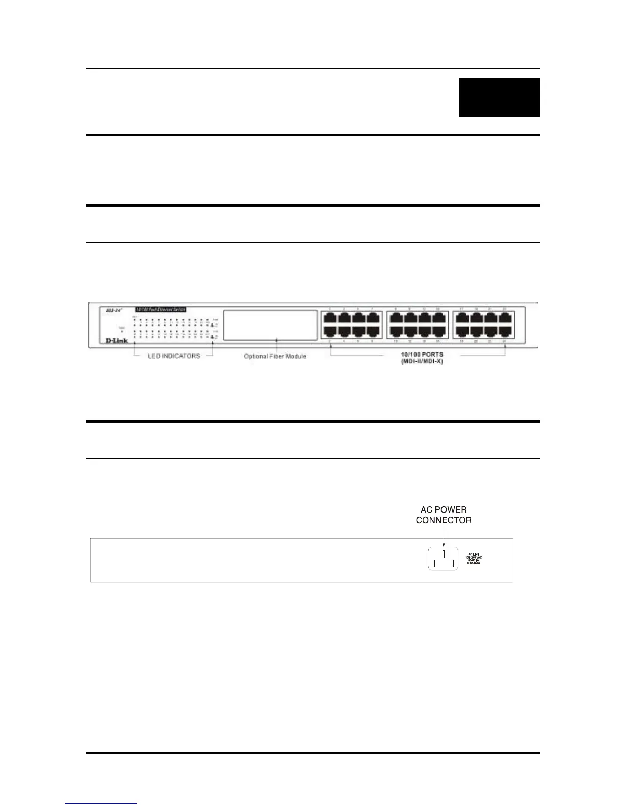
The front panel of the Switch consists of 24 (DSS-24+) 10/100
Mbps MDI/MDI-X ports and LED indicators.
Figure 3.1 Front panel view of the DSS-24+ Switch
Rear Panel
The rear panel of the Switch consists of an AC power connector.
Figure 3.2 Rear panel view of the DSS-24+ switch
♦ AC Power Connector This is a three-pronged connector
that supports the power cord. Plug in the female connector
of the provided power cord into this connector, and the male
connector into a power outlet. Supported input voltages
range from 100 ~ 240 VAC at 50 ~ 60 Hz.