6
DRAWING AND PART FILE
MODEL
NAME:
LOWER_ATTACHMENT_EXPLODED(EPSON)_NO_IR
MODEL
LOCATION:
S:\Engineering\Solidworks Files\EPSON IDEA\INSTRUCTIONS\
SHEETS:
1 OF 1
THE INFORMATION AND DESIGNS CONTAINED IN THIS DRAWING ARE CONFIDENTIAL
AND PROPRIETARY PROPERTY OF MILESTONE AV TECHNOLOGIES NEITHER THIS
DESIGN NOR ANY INFORMATION CONTAINED IN THIS DRAWING MAY BE
REPRODUCED OR DISCLOSED TO OTHERS WITHOUT EXPRESS WRITTEN CONSENT
OF MILESTONE AV TECHNOLOGIES.
THIS PRINT SUPERSEDES ANY
PRINT DATED PRIOR TO:
PART NO:
26206
5/30/2014
REVISIONS
REV.
DESCRIPTION
CHNGD BY:
DATE:
APPR'D BY:
TOLERANCES:
DECIMAL:
.XX = ±.010
.XXX = ±.005
FRACTIONAL:
= ±.015
ANGULAR:
= ±1°
1:18
DRAWN BY:
ADW
DATE:
4/16/2014
APP'D BY:
DATE:
X.XXXX
1/19/2011
MATERIAL NO:
MULIT
FINISH:
TYPE OF FINISH
sw
NAME:
EXPLODED VIEW FOR INSTRUCTIONS
SCALE:
DA-LITE SCREEN CO.
WARSAW, INDIANA, USA
PART NO:
26206
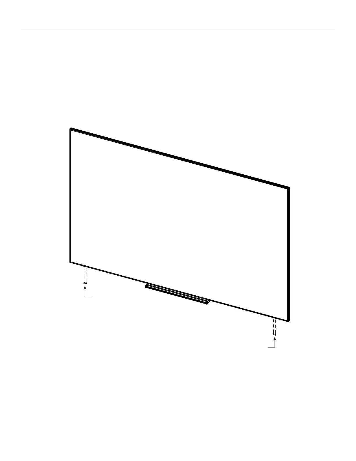
Wall Mounting Instructions (continued)
5. Tap the bottom of the two L-brackets with the rubber mallet until
they make contact with the frame. Secure the two L-brackets to
the frame with the remaining (4) #8 x ½" screws (Figure 3).
6. Attach the bottom of the screen to the wall through the mounting
holes located under the marker tray.
#8 X ½" Screws
Figure 3
#8 X ½" Screws