47
2.1.1) has been placed close to the system entry door, the quantity of
water with which to ll the system should be 0,9 litres. It is recommended
to t the non-return valve at the end of the suction pipe (foot valve) so as
to be able to ll it quickly too during the loading operation. In this case the
quantity of water necessary for the loading operation will depend on the
length of the suction pipe (0,9 litres + …).
Installation “below head” (par. 2.1.1): if there are no check valves between
the water deposit and the system (or if they are open), it loads automati-
cally as soon as it is allowed to let out the trapped air. So slackening the
lling cap (Fig.3_point 6) enough to vent the trapped air allows the system
to load completely. You must survey the operation and close the loading
door as soon as the water comes out (however it is recommended to t a
check valve in the section of the suction pipe and to use it to control the
loading operation with the cap open). Alternatively, in the case where the
suction pipe is intercepted by a closed valve, the loading operation may be
carried out in a similar way to the one described for installation over head.
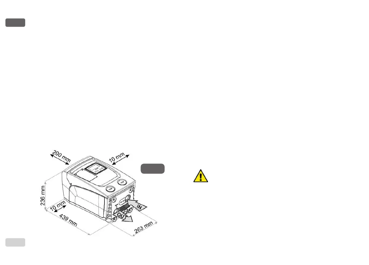
2.2 - Horizontal Conguration
Screw the 4 rubber feet supplied loose in the package into the brass seats
in face E. Put the system in place, taking into account the dimensions in
Fig.8.
Figure 8
• The distance of at least 10mm between Face B of the system and
an obstruction is obligatory to let out the power supply cable to the
mains socket.
• The distance of at least 200mm between Face A of the system and an
obstruction is recommended so as to be able to remove the door and
gain access to the technical compartment.
If the surface is not at, unscrew the foot that is not touching and adjust
its height until it contacts the surface so as to ensure the stability of the
system. The system must in fact be placed in a safe and stable position,
ensuring that its axis is vertical: it must not be in an inclined position.
2.2.1 Hydraulic connections
Make the connection at input to the system through the mouth on Face C
marked “IN” in Fig. 8 (suction connection). Then remove the cap using a screw-
driver. Make the connection at output from the system through the mouth on
Face C marked “OUT 1” in Fig. 8 and/or through the mouth on Face F marked
“OUT 2” in Fig. 8 (delivery connection).
In this conguration either of the 2 mouths can be used as an alternative to
the other (depending on the convenience of the installation), or simultaneously
(dual delivery system). Then remove the cap(s) from the door(s) you intend
to use with a screwdriver.
All the hydraulic connections of the system to the plant to which it can be con-
nected are of the threaded female type 1” GAS, made of brass.
See WARNING for Figure 7.
2.2.2 Orientation of the Interface Panel
The Interface Panel has been designed so that it can be oriented in the
direction where it is most convenient for the user to read: its square shape
allows it to be rotated from 90° to 90° (Fig.9).