Technical Manual - Page 13
Electrode Detection of a Gas Flame
Theory of Operation
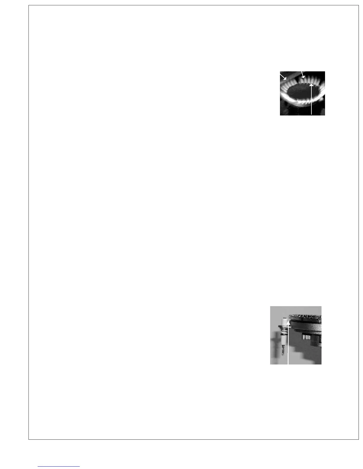
If you look closely at a fi nger of burner fl ame you will see that it is
clearly made up of three separate elements:
(see fi gure 1)
1. Inner fuel rich cone
2. *Ionized blue outer cone with current carrying capabilities
3. Outer air rich mantle.
When gas combined with air; burned energy is released in the form
of heat and light. When the gas / air mixture is controlled, the outer
blue cone will actually carry electrical current similar to a wire.
If we place a metal probe into this “Ionized Plume” and apply a voltage between it and the burner,
current will fl ow. An important characteristic of a burner/fl ame/electrode assembly is its ability to
mainly pass current in one direction. It behaves as a one way valve or rectifi er.
Flame Rectifi cation systems make use of this directional characteristic when detecting a good
fl ame to distinguish it from leakage currents that can arise due to moisture contamination, soiled
igniter tip, poorly grounded burner spreader ring / burner head, cracked igniter insulation or poor
house ground.
A voltage of alternating polarity (an AC voltage) is applied to the electrode from the spark module
and the resultant current fl ow which is greater in one direction than the other, is electronically
detected. This current is very small, about one microamp (one millionth of an amp).
The Dacor re-igniter has a specifi ed minimum fl ame current that will be sensed as a fl ame of
0.5 microamps (1.3uA minimum sensitivity for C664 Series Gas Ignition Systems). The minimum
recommended fl ame current measured under all likely conditions in an installation should be 1.0
microamps for re-igniters (2.0 microamps for C664 Series). When a burner fl ame is present the
Ionized outer cone will be producing a small DC current. This current is known as (Flame Current).
The fl ame current has to be at a certain level to allow voltage from the spark module to fl ow
effi ciently.
The accurate placing of the electrode in the fl ame is important.
This igniter tip needs to be perfectly located in the ionized outer
blue cone to effectively send and then detect current fl ow.
To break it down further, the spark module
acts as a simple capacitor. It saves voltage like a sponge
until it can hold no more. It will save and release this voltage
approximately 3 times per second. When the voltage is released it follows the spark wire until
reaches the spark electrode tip. The built up voltage wants to leave the tip and move to the
point of least resistance. In a healthy situation this will be the burner spreader ring. From the
burner spreader ring the voltage fl ow will pass through the burner head, burner tube, chassis and to
ground. An interruption of this current path will cause the spark system to misbehave.
3
Figure 1
1
2