Technical Manual - Page 34
that the Molex plug is securely attached to the main PCB.
B. Unit will not raise or lower:
1. Check limit switches and the connecting wiring.
2. Check main PCB between L3 and N3 for 120 VAC when the UP/DOWN key is pressed. If
voltage is not present check between terminals #12 and #13 on the PCB for continuity when
the up/down key is depressed. If there is no voltage or continuity the PCB is defective and
must be replaced.
C. Vent will go up but motor will not run:
1. Check for proper wiring to the exhaust motor. The majority of motors failing to operate on new
units are the result of incorrect installation wiring.
2. Look for miswired or defective limit switches. Review the functional and operational descrip
tions of the limit switches.
3. Check voltage output to exhaust motor. This should be 120VAC on the high-speed setting.
4. Raise the vent or press the high-speed button. Spin the exhaust motor, if motor runs check
capacitor.
5. Check for defective PCB. See section on PCB Diagnosis.
D. Vent will not stop, goes up and down continuously:
1. Check for misaligned or defective limit switches.
2. Check wiring between the limit switches and main PCB.
E. Blower runs only when the vent is down.
1. Check for proper wiring at the PCB
2. Check for defective limit switches
3. Check for defective PCB. See section on PCB Diagnosis.
F. Vent only goes part way up; user must push keypad repeatedly.
1. Check for a loose wiring harness or loose wire connections.
2. Check for dirt or grease on the Touchpad and Contact board. See section on KeyPad
diagnosis.
3. Check for defective PCB. See section on PCB diagnosis.
G. Vent operates by itself:
For this to occur the main PCB is detecting some type of electrical interference. Check for the
following:
1. The installation instructions require a correctly grounded and dedicated circuit. If the unit is
connected to a non-dedicated circuit refer the customer back to the installer and inform them
that they will be responsible for future repairs until the wiring is corrected.
2. If the problem can be traced or associated with the use of an electronic gas cooktop (of any
design) then a fi lter assembly (part number 86325) should be installed.
H. Filter light stays on:
1. If the fi lter light remains on after the fi lter button is depressed remove power to the unit to
deposit to replace the P.C.B
2. If the light remains on after resetting the microprocessor, replace the main PCB
I. Main PCB keeps shorting out:
1. Check for reversed polarity on the incoming power supply.
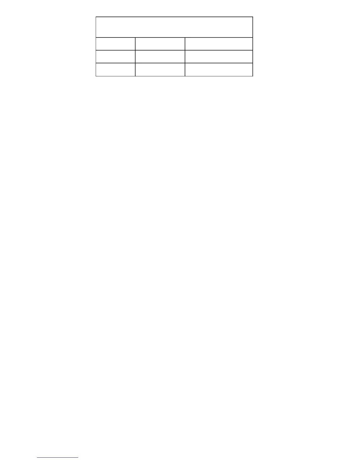
deepSnaFroFtuptuOegatloV
rotomnaftsuahxeehtotBCPniamehtmorftuptuo
woL
CAV77CAV78
muideM
CAV49CAV101
hgiH
CAV51
1CAV511