18
8. Power supply (STR F6653)
8-1. STR-F6653 general description
The STR-F6653 is an hybrid IC with a build-in MOSFET and control IC, designed for flyback converter type switch mode power
supply applications.
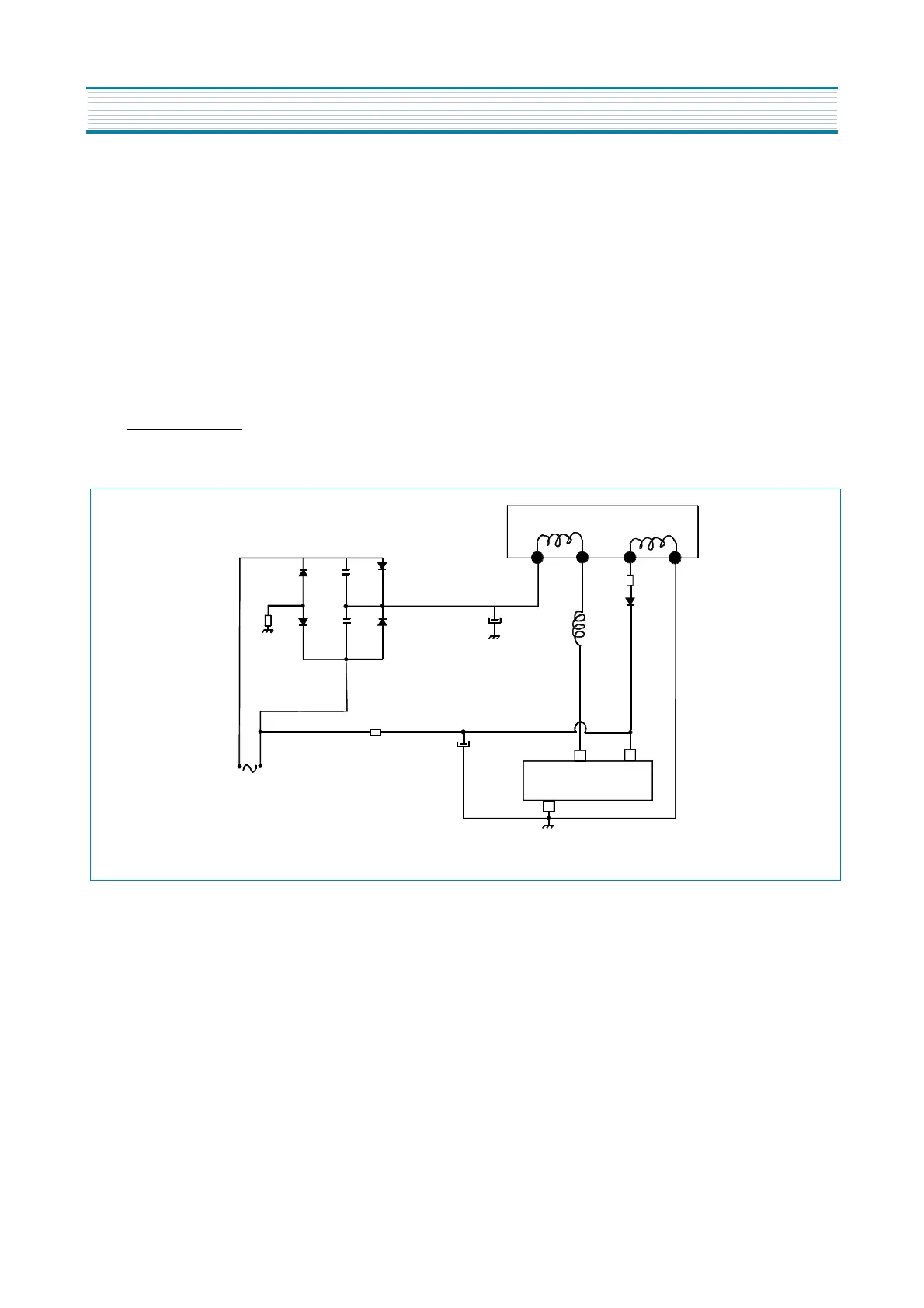
8-2. Power supply primary part operations
An oscillator generates pulse signals which turn on and off a MOSFET transistor.
8-2-1. Start -up circuit: V
IN
The start-up circuit is used to start and stop the operation of the control IC, by detecting a voltage appearing at the V
IN
pin (pin 4).
When the power switch i
s
pushed on, V
IN
increases slowly. During this time, C806 is charged through R802.
As soon as V
IN
reaches 16V, the STR-F6653 control circuit starts operating. Then, V
IN
is obtained by smoothing the winding volt-
age which appears between pin 6 and pin 7 of the SMPS transformer.
As this winding voltage does not increase to the set voltage immediately after the control circuit starts operating, V
IN
starts drop-
ping. However, as this winding voltage reaches the set value before V
IN
voltage drops to the shutdown voltage (at 11V), the con-
trol circuit continues operating (see below, V
IN
voltage at start-up). Resistor R805 prevents variations of voltage at the V
IN
pin, as
some regulation of the SMPS transformer occurs due to secondary side output current
V
IN
must be set higher than the shutdown voltage (V
IN
(off) = 11V
max
) and lower than the O.V.P. (overvoltage protection) operat-
ing voltage (V
OVP
= 20.5V
min
).
R819
D802
D801
D803
D804
C804
C803
R802
C806
C805
Main AC voltage
2
7
6
4
D805
R805
L801
4
Ground
Drain Vin
T801 SMPS TRANS
3
I801 STR-F6653
5
APPENDIX
FUNCTIONAL DESCRIPTION