23
9-1-4. Reset pulse circuit operations description
- When DC supply voltage from I823 regulator starts rising (from 0V to 1.2V), no current flows through D591 zener diode. So,
Q510 is in off mode.
Also V
be Q511
=Vcc/2 -Vcc = -Vcc/2 > -0.6V. So, Q511 is in off mode.
Then, no voltage reaches I501 pin 60.
- When this voltage reaches 1.2 V, Q510 stays in off mode
but V
be Q511
= -0.6V. So, Q511 is switched on and starts driving DC supply voltage to I501 pin 60.
- When the DC supply voltage reaches (2.4V +0.6V ) =3.0V, Q510 starts conducting but as the Q511 base-emitter voltage is the
same as the collector-emitter voltage of the saturated Q510, Q511 switches off and no voltage reaches I501 pin 60.
- If the DC supply voltage decreases below 3 V, Q510 switches off immediately. Q511 starts conducting, pulling I501 pin 60
high. At the same time, it discharges the reset capacitor C501. Discharging this capacitor is necessary to guarantee a defined
reset pulse duration.
9-2. TV normal run and stand-by mode operations
Depending on remote control commands, I501 microcontroller part pin 63 (power) is set to:
- high for normal run mode
- low for stand-by mode
9-2-1. TV on normal run mode
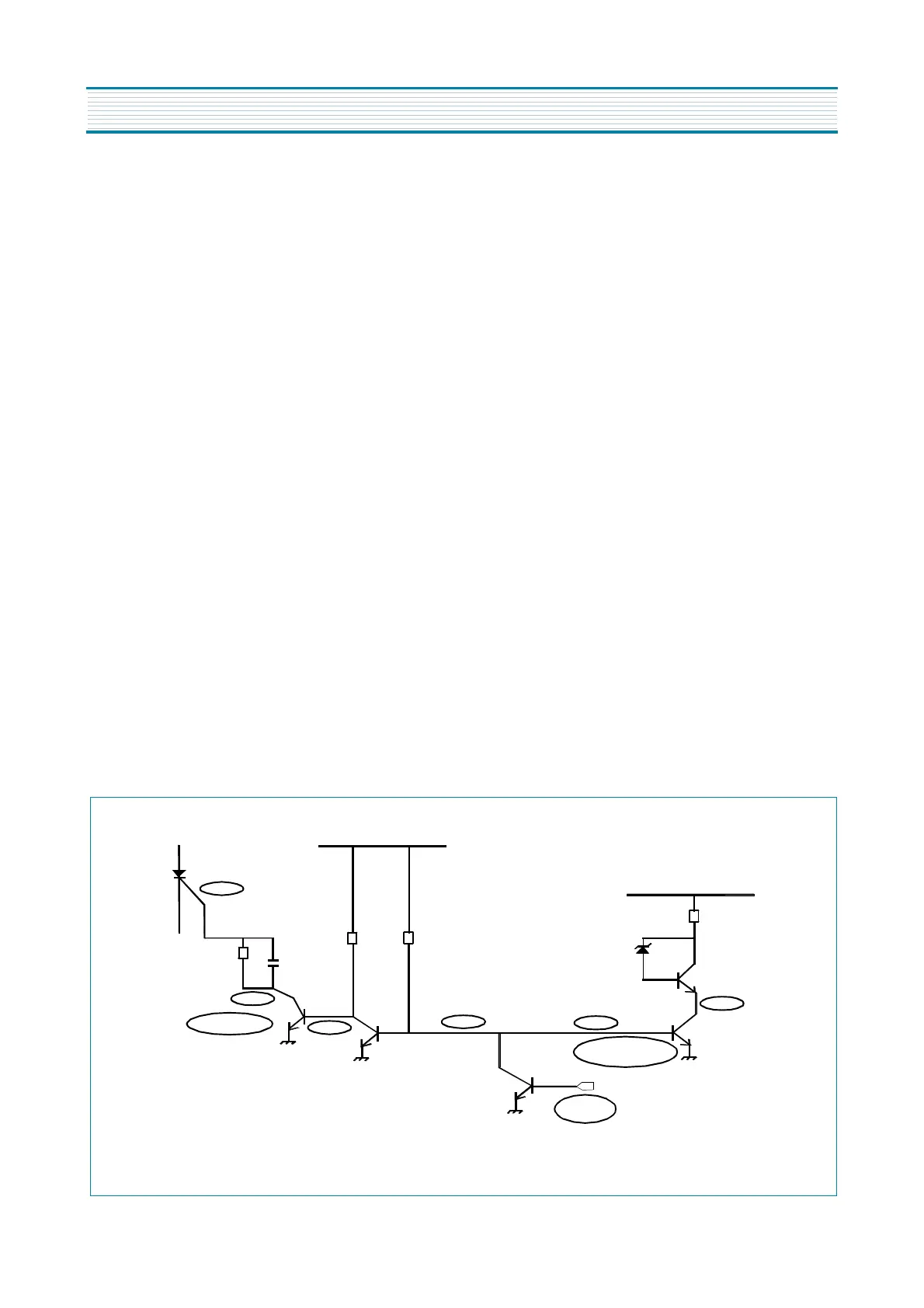
9-2-1-1. I501 microcontroller part pin 63 (power) effect
I501 microcontroller part pin 63 (power) is connected to the following circuit:
I810
CONTROLLED
RECTIFIER
R820
R830
C830
R829
Q808
6V DC
11V DC
R870
D811
Q811
Q809
Q807
Q810
LOW
LOW
LOW
LOW
HIGH
HIGH
CONDUCTING
POWER
HIGH
NOT
CONDUCT
ING
I501 microcontroller part pin 63 (POWER) effect
APPENDIX
FUNCTIONAL DESCRIPTION