24
In normal run mode, I501 microcontroller pin 63 (power) is set to high
So, I810 controlled rectifier is not conducting
- Q809 is conducting. So, Q808 is not conducting and Q807 is conducting
- So, Q807 collector is connected to the ground and I810 controlled rectifier gate pin is set to low (no conducting)
So, current from 11V DC voltage (from T801 SMPS transformer pin 13) does not flow through Q811 and Q810
transistors but flows through I806 IC error amplifier
- Q809 is conducting. So, Q810 is not conducting and no current flows from Q810 collector to the ground
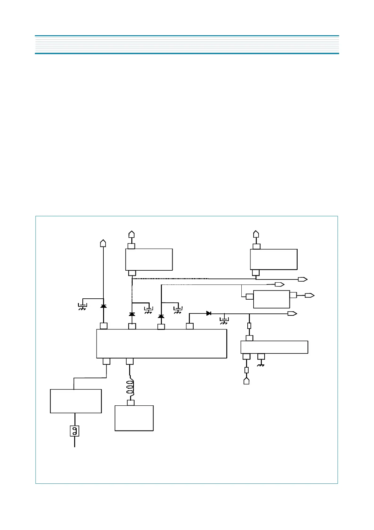
Therefore, the power circuit diagram is the following one:
9-2-1-2. power supply circuit diagram during TV set normal run
I820
5V
REGULATOR
I823
3.3V
REGULATOR
14.5V (CP785)
12.5V (CP385)
5V
3.3V
3
3
1
1
11V
8V
6V
1
3
143V (CP785)
123V-113V (CP385)
D820
D860
D830
D831
C832
C823
C861
9
12
13
16
2
4
C813
R823
R810
11V
2
3
I806
IC ERROR AMPLIFIER
14.5V
12.5V
8.5V
8V
11.5V
11V
143V
123V / 113V
T801 SMPS TRANSFORMER
D801... D804
(GRAETZ BRIDGE)
D
I801
MOSFET AND
CONTROL IC
SW801
POWER
SWITCH
MAIN AC VOLTAGE
L801
I822
8
V
REGULATOR
1
3
Power supply operation during TV set normal run
APPENDIX
FUNCTIONAL DESCRIPTION