-14-
6. Adjusting Method
6-1. MODULE POWER Adjustments and Test Point Locations
• Video pattern condition : 100 IRE Full White Pattern
• Adjust voltages (Vadd, Vsus) to the values that module maker labeled on the PDP panel.
If there are some problems in picture after adjusting, you should classify
that PDP module as a fault and contact to PDP module maker.
1) Vd (Vadd Voltage) : Data address voltage
- Measurement equipment : Digital Volt Meter (DC Volt mode)
- TP : P812 #3
- Adjusting Volume : VR901
- Adjusting Voltage : Voltage written in the Label, which is located in the upper
middle side of PDP Module. (Typical Voltage : 55 ~ 66 V)
2) Vs (Vsus Voltage) : Sustain voltage
- Measurement equipment : Digital Volt Meter (DC Volt mode)
- TP : P812 #9
- Adjusting Volume : VR951
- Adjusting Voltage : Voltage written in Label, which is located in the upper middle side
of PDP Module. (Typical Voltage : 180 ~ 200 V)
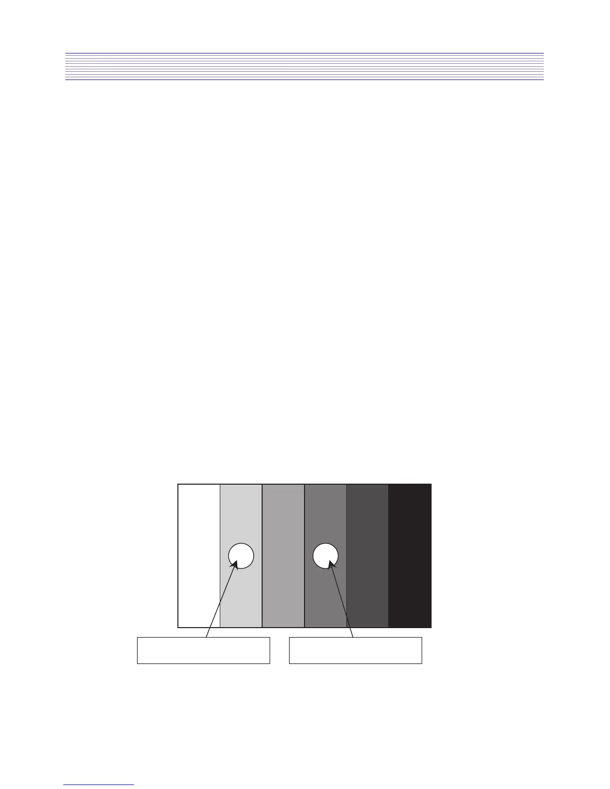
6-2. White Balance Adjustments
1) Apply 5 Step Gray Scale pattern to Video input terminal
2) Check initial data of User Menu [refer to 4-1. Picture (dynamic)]
3) To enter Service mode, press button “VOL DOWN -> MUTE -> RECALL -> MUTE”
on the remote control and select PW338_1, then check initial data of Service mode
[refer to 5. Service Mode].