- 65 -
Service manual WP 895/895F, CP885/885F, CP485F
*
power supply functioning during TV set normal run mode
- I801 transmits controlled pulses to T801 which generates DC voltages after rectifications by secondary part diodes
and electro capacitors (by example by D820 and C813 on 143V supply voltage line).
- 8V, 5V, 3.3V supply voltage lines have stabilized voltages obtained by I820, I822, I823 voltage regulators.
- On 143V supply voltage line, R823 resistor has been chosen to reach exact DC voltage required on this line.
- 143V supply voltage line includes an IC error amplifier (I806) which corrects unexpected DC voltage variations on
this line.
*
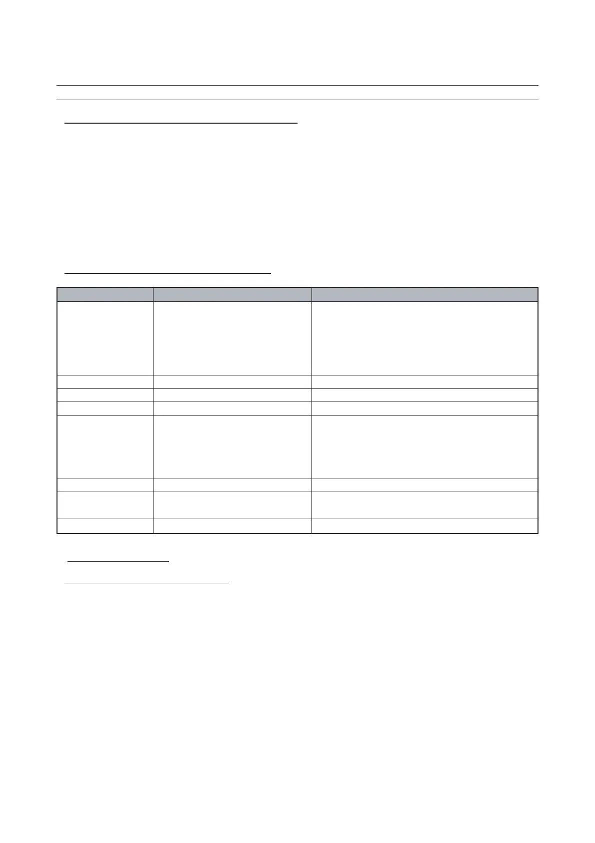
power supply IC delivery during TV set normal run
power supply line IC power supply delivery Remarks
143V FBT
FBT supplies 43V to I301 vertical IC
FBT supplies 43V to T401 H-Drive
FBT supplies 12V to I301 vertical IC
FBT supplies 33V to the tuner
FBT supplies 188V to I901 video amplifier pin 6
14.5V I602 sound amplifier pins 3-16
14V T401 H- drive
8V
I601 Sound Demod pins 38-39-40
5
V
I703 IR receiver pin 1
I501 Main IC Pin 3
I501 Main IC Pin 54
I501 Main IC pins 3-15-45
I101 If IC Pin 23
I601 Sound Demod pins 7-18-57
I702 EEPROM pin 8
tuner
3.3V
S/B 5V
S/B 3.3V
I501 Main IC pin 25
b) TV set on stand-by mode
*
TV set circuit diagram on stand-by mode