©
200423 3-19
Inspection and adjustment
EXPLANATORY NOTES ON THE MAINTENANCE ACTIVITIES
ΞΦ95 series
5
3.23 INSPECTING THE AUTOMATIC BRAKE ADJUSTER
Brake drum
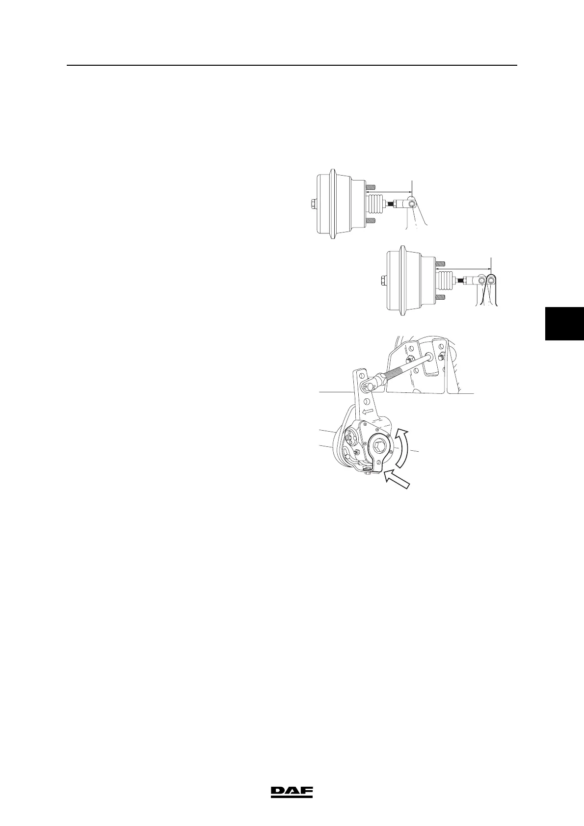
Inspection, brake adjuster travel
1. Measure the basic setting L1.
2. Measure the position when the brakes are
applied, L2 (minimum brake system
pressure 6 bar).
3. Calculate the brake stroke L3 = L2 - L1, see
"Technical data". If the brake stroke differs
from the specified value, take the following
action:
4. Check whether the control plate (1) is locked
in respect of the fixed bracket.
5. If not, turn the control plate as far as possible
(until the internal stop is felt) in the direction
in which the brake adjuster is moved during
braking.
6. Fix the control plate in this position using the
attachment nut on the fixed bracket.
7. Check the internal slip using a torque
wrench.
Inspection, internal slip
1. Make certain that there is sufficient pressure
in the reservoirs (6.5 bar minimum).
2. Release the parking brake.
3. Fit a torque wrench on the hexagonal
adjusting bolt and turn this counter-
clockwise. For the permitted value, see
"Technical data".
If the specified reverse torque is not
reached, but the worm shaft already turns at
a lower value, the brake adjuster should be
replaced.
M6101
L2
L1
M6005
1