User’s Manual
1
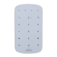
Table 3-1 Structure
No. Name Description
1 Indicator
There are four indicators, including communication, arming
and disarming, fault, and alarm indicators.
●
All indicators are solid for 2 seconds: Powered on.
●
All indicators are off: Not enter paring mode.
●
Communication indicator status:
◇
Flashes green quickly: Pairing mode.
◇
Sold green for 2 seconds: Pairing successful.
◇
Flashes green 3 times: Pairing fails.
◇
Off: Online.
◇
Flashes green slowly and other indicators are off:
Offline.
◇
Flashes green slowly and other indicators are in the
normal status: Enters into reduced sensitivity mode.
●
Arming and disarming indicator status:
◇
Solid blue: A single or more rooms are armed.
◇
Flashes green 3 times and then off: All rooms are
disarmed.
●
Fault indicator status:
◇
Flashes yellow: Fault alarms are triggered.
◇
Off: A single or more rooms are armed, or no fault
occurs.
●
Alarm indicator flashes red: Alarm are triggered.
2 Key
15 keys.
●
Numeric keys: 0-9.
1 is also the fire alarm key, 2 emergency alarm key, and 3
medical alarm key.
●
#: Search.
●
*: Space.
●
Home arming.
●
: Away arming.
●
: Disarming.
3 Card swiping area Supports IC card recognition. You can swipe your card here.
4 Back cover
When the tamper switch is released, the tamper alarm will be
triggered.
5 On/off switch Turn on or turn off the keypad.
6 4 × Batteries Insert batteries to power on the keypad.
7 Tamper switch
When the tamper switch is released, the tamper alarm will be
triggered.
 Loading...