3
1.7 Rear Panel
Please note the following contents are based on our 2U 960H series product. For detailed
operation instruction of other series products, please refer to the User’s Manual included
in the resources CD.
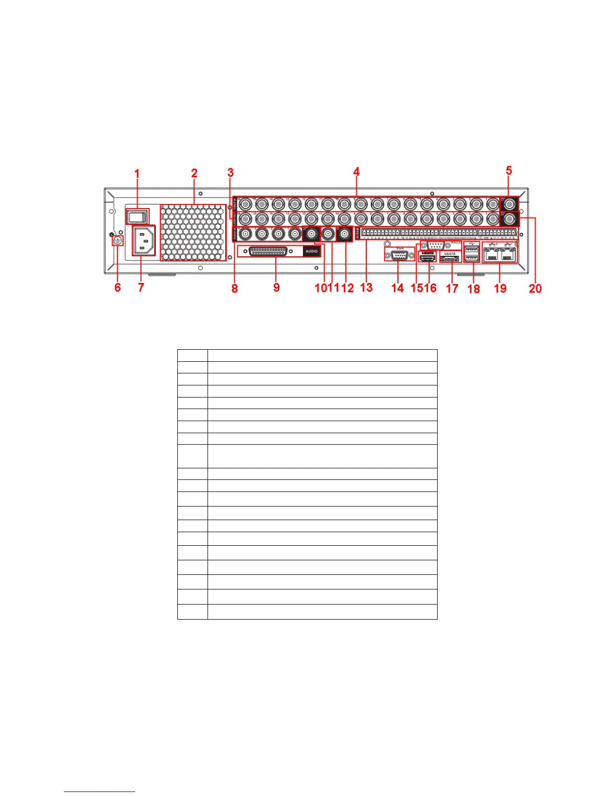
This series DVR rear panel is shown as below. See Figure 1-1.
Figure 1-1
Please refer to the following sheet for detailed information.
1 Power button
2 Fan
3 Loop video output
4 Video input
5 Video output
6 Grounding hole
7 Power input port
8 Audio input port
9 DB25 port (the 5th to the 16th-channel audio
input port)
10 Audio output
11 Bidirectional talk input port
12 Bidirectional talk output port
13 Alarm input/alarm output/RS485 port
14 Video VGA output
15 RS-232 port
16 HDMI port
17 eSATA port
18 USB port
19 Network port
20 Video SPOT output
When connect the Ethernet port, please use crossover cable to connect the PC and use the
straight cable to connect to the switcher or router.
1.8 Connection Sample
Please note the following contents are based on our 2U 960H series product. For detailed
operation instruction of other series products, please refer to the User’s Manual included
in the resources CD.
 Loading...