GND Ground port.
OUT Video output port.
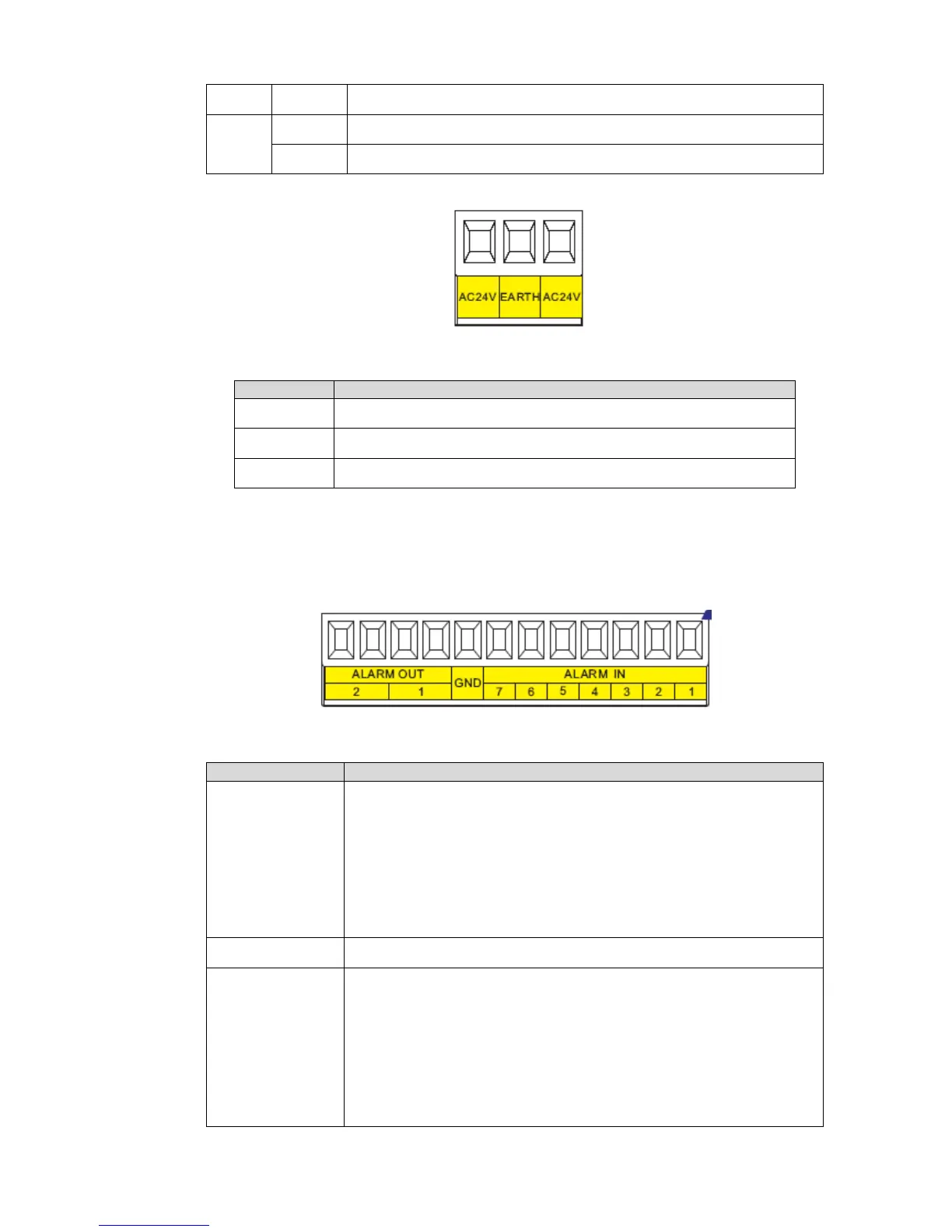
Power port connection interface is shown as in Figure 3-3.
Figure 3-3
Name Function
AC24V 24V power port. Connect to the power cable.
EARTH Ground port.
AC24V 24V power port. Connect to power cable.
3.2 Alarm Cable Connection
Open the dome cover and take PTZ chip core out. Turn the core upside down; you can see the alarm port.
See Figure 3-4.
Figure 3-4
Name Function
Alarm out:1-2
Two alarm output channels. When there is an alarm from current
channel, system activates relay or not.
Alarm output relay default setup is NO. You can use the jump-
cap near the power board relay to set.
NO:Normal open alarm output.
NC:Normal close alarm output.
GND Alarm input ground end.
Alarm in:1-7
Seven alarm input channels. It is to receive relay signal from the
external alarm source. You can go to dome menu to activate
specified preset or patter.
When the activation mode is NO (normal open), dome alarms
when there is low voltage. High voltage will not activate the
alarm.
When the activation mode is NC (normal close), dome alarms
 Loading...