16 WGZ030D through WGZ200D OMM 1130
Automatic Pumpdown
WGZ units are equipped with single pumpdown control. When the last compressor running on either
circuit is ready to shut off, the liquid line solenoid valve (LLSV) is closed first and the compressor
continues to run until the pumpdown pressure is reached, at which time the compressor shuts off. The
shut off pressure is set at 15 psi below the Low Evaporator pressure Unload setpoint.
When the first compressor on a circuit starts, the LLSV opens simultaneously.
Manual Pumpdown
When the Pumpdown Switch is in the pumpdown position, all compressors except #1 and #2 will shut off.
Then the Liquid Line and Hot Gas Bypass Valves will close. The operating compressor will pump out the
refrigerant. When the Suction Pressure is at 40 psig, the compressors will stop.
Chilled Water and Condenser Water Pumps
The chiller MicroTech II controller can be programmed to start and stop the system chilled water and
condenser water pumps. They may also be controlled by the BAS or manually. Programming directions
and the sequence of operation can be found beginning on page 39.
Cooling Tower Control
The cooling tower fans and/or the tower bypass valve can be controlled by the MicroTech II controller.
This provides a simple and direct method to control the unit’s discharge pressure. Programming
directions and the sequence of operation can be found on page 67. Some means of discharge pressure
control m
ust be installed if the condenser water temperature can fall below 60F (16C).
Condenser Fan Control
Model AC chillers equipped with air-cooled or evaporative-cooled condensers usually require some form
of discharge pressure control. The MicroTech II controller can be programmed to provide this function
by cycling condenser fans based on the unit discharge pressure. Directions on the pressure settings can be
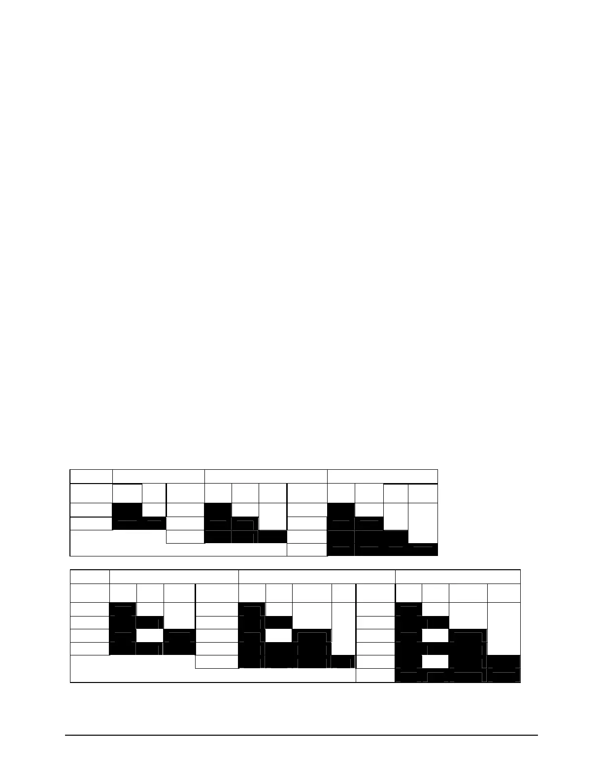
found on page 67. The following charts illustrate how four controller outputs can control six fan steps.
Circuit 1
Number of Fans = 4 Number of fans = 6 Number of fans = 8
Stage #
Fan
1
Fan
3 Stage #
Fan
1
Fan
3
Fan
5 Stage #
Fan
1
Fan
3
Fan
5
Fan
7
1
ON
1
ON
1
ON
2
ON ON
2
ON ON
2
ON ON
3
ON ON ON
3
ON ON ON
4
ON ON ON ON
Number of fans = 8 (R410A)Number of fans = 10 (R410A)Number of fans = 12
Stage #
Fan
1
Fan
3
Fan
5&7 Stage #
Fan
1
Fan
3
Fan
5&7
Fan
9 Stage #
Fan
1
Fan
3
Fan
5&7
Fan
9&11
1 ON 1 ON 1 ON
2 ON ON 2 ON ON 2 ON ON
3 ON ON 3 ON ON 3 ON ON
4 ON ON ON 4 ON ON ON 4 ON ON ON
5 ON ON ON ON 5 ON ON ON
6 ON ON ON ON


 To Next Page