70 WGZ030D through WGZ200D OMM 1130
Stage Mode (above) except that (1) it shall be kept at zero until the first fan stage is ON, and (2) the
following setpoints do not apply.
Valve Control Range (Min)
Valve Control Range (Max)
Val v e Ty p e
Valve Type settings are NC (normally closed to tower) or NO (normally open).
These settings establish the operation of a tower bypass valve (must be a 3-way valve).
Initial Valve Position
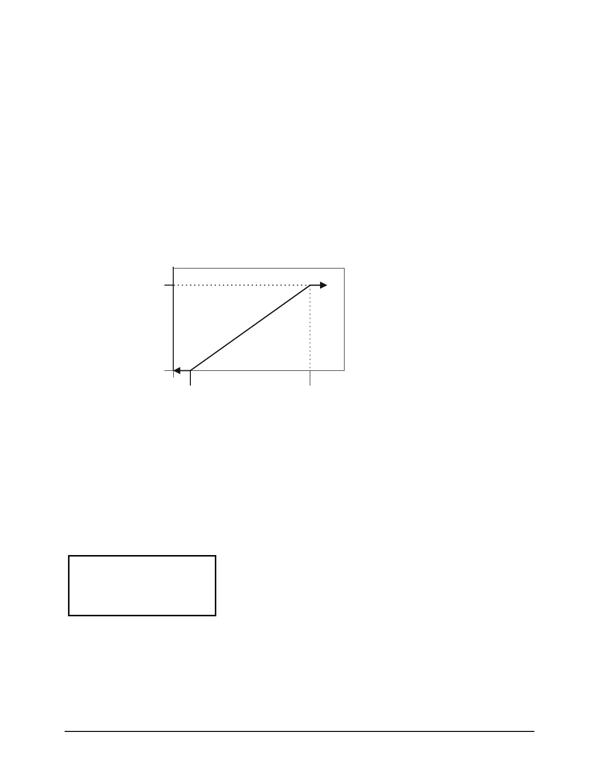
When the condenser pump is not in the RUN state, the valve output shall be set as a function of entering
condenser water temperature (ECWT) per the following graph.
Figure 11, Initial Valve Position
Max Position @
Setpoint
(90°F)
Min Position @
(60°F)
Min Start Position
(10%)
Initial Valve Position
(values are examples only)
Max Start Position
(90%)
Setpoint
Setpoint
Setpoint
Operation After Start
When the condenser pump is in the RUN state, the valve output shall be controlled in one of two modes
as specified by the Valve/VFD Control setpoint. The controlled parameter shall be the condenser entering
water temperature. When the desired output signal varies from 0 to 100%, the output voltage shall vary
as shown below.
0 to 10 VDC (Valve Type = NC)
10 to 0 VDC (Valve Type = NO)
Water-cooled = Y
SET TOWER SPs (5)
Valve SP = XXX F
Valve DB = XX.X F
Valve SP is the minimum tower water temperature acceptable, default is 65F.
Valve DB is the dead-band in degrees, default is 2.0F.
 Loading...