pressUre drop daTa
www.DaikinApplied.com 33 IOM 1206-7 • TRAILBLAZER
®
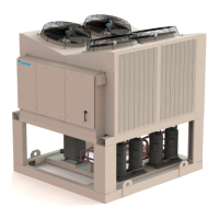
MODEL AGZ CHILLERS
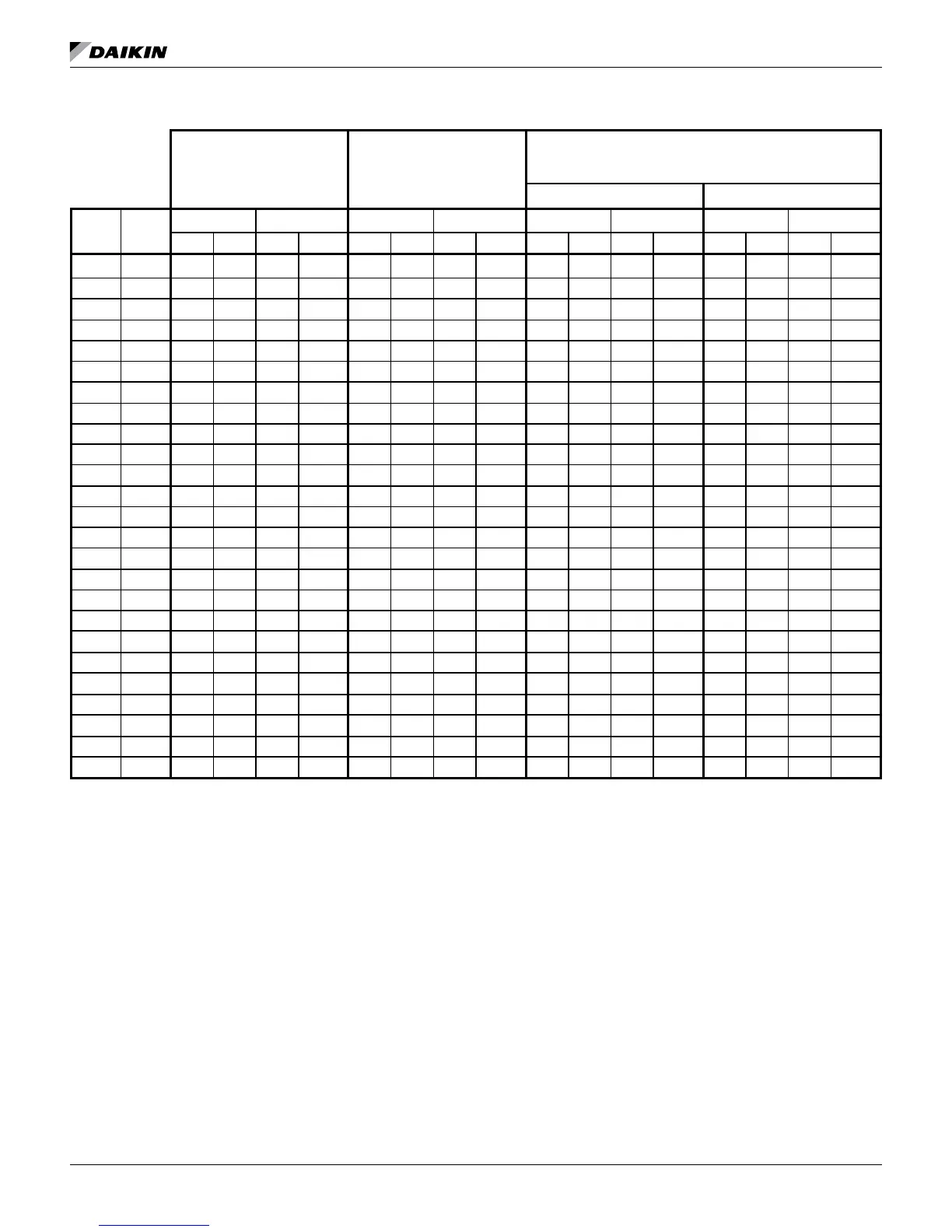
Table 11: Pressure Drop Data
Part Load Minimum Flow
(Variable Flow Systems Only
Full Load Minimum Flow
(Applies to Constant and
Variable Flow Systems)
Fixed and Variable Flow Systems
Minimum Flow Rate
2
Minimum Flow Rate
1
Nominal Flow Rate Maximum Flow Rate
Curve
Ref.
Model
IP SI IP SI IP SI IP SI
GPM DP ft. lps DP kpa GPM DP ft. lps DP kpa GPM DP ft. lps DP kpa GPM DP ft. lps DP kpa
A 030E 27.0 1.7 1.7 5.1 42.2 4.0 2.7 12.0 67.4 9.8 4.3 29.4 112.4 26.0 7.1 77.7
B 035E 33.5 2.4 2.1 7.1 52.4 5.6 3.3 16.7 83.8 13.7 5.3 40.9 139.6 36.4 8.8 108.7
C 040E 37.1 2.5 2.3 7.4 57.9 5.8 3.7 17.3 92.6 14.2 5.8 42.5 154.4 37.7 9.7 112.6
D 045E 40.9 2.3 2.6 6.8 63.9 5.3 4.0 15.8 102.2 13.2 6.5 39.4 170.4 34.4 10.8 102.7
E 050E 46.4 2.7 2.9 7.9 72.5 6.2 4.6 18.5 115.9 15.2 7.3 45.3 193.2 40.0 12.2 119.6
F 055E 49.7 2.3 3.1 7.0 77.7 5.5 4.9 16.3 124.3 13.4 7.8 40.0 207.2 35.6 13.1 106.2
G 060E 54.0 2.3 3.4 6.9 84.3 5.4 5.3 16.1 134.9 13.1 8.5 39.3 224.8 34.7 14.2 103.6
H 065E 55.5 2.4 3.5 7.3 86.7 5.7 5.5 17.0 138.7 13.9 8.8 41.4 231.2 36.6 14.6 109.3
I 070E 61.5 3.0 3.9 8.8 96.1 6.9 6.1 20.6 153.8 16.9 9.7 50.4 256.4 44.5 16.2 133.0
J 075E 69.8 1.2 4.4 3.6 109.1 2.8 6.9 8.4 174.5 6.9 11.0 20.5 290.8 18.2 18.3 54.3
K 080E 73.8 1.2 4.7 3.7 115.4 2.9 7.3 8.6 184.6 7.1 11.6 21.3 307.6 18.9 19.4 56.6
L 090E 80.1 1.4 5.1 4.3 125.1 3.4 7.9 10.1 200.2 8.3 12.6 24.8 333.6 22.1 21.0 66.1
M 100E 92.4 1.3 5.8 4.0 144.3 3.2 9.1 9.5 230.9 7.8 14.6 23.3 384.8 20.8 24.3 62.2
N 110E 102.0 1.4 6.4 4.2 159.5 3.3 10.1 9.9 255.1 8.2 16.1 24.4 425.2 21.6 26.8 64.6
O 120E 113.1 1.5 7.1 4.5 176.7 3.6 11.1 10.7 282.7 8.8 17.8 26.4 471.2 23.5 29.7 70.3
P 130E 119.5 1.5 7.5 4.4 186.8 3.5 11.8 10.4 298.8 8.6 18.9 25.7 498.0 22.9 31.4 68.3
Q 140E 128.9 1.7 8.1 5.1 201.5 4.0 12.7 12.1 322.3 9.9 20.3 29.7 537.2 26.4 33.9 79.0
R 150E 143.6 1.8 9.1 5.5 224.4 4.4 14.2 13.0 359.0 10.8 22.7 32.4 598.4 29.1 37.8 87.0
S 161E 143.6 1.8 9.1 5.5 224.4 4.4 14.2 13.0 359.0 10.8 22.7 32.4 598.4 29.1 37.8 87.0
T 170E 154.1 1.9 9.7 5.6 240.8 4.5 15.2 13.4 385.2 11.2 24.3 33.4 642.0 30.2 40.5 90.2
U 180E 164.8 2.3 10.4 6.9 257.6 5.3 16.2 15.9 412.1 12.8 26.0 38.3 686.8 33.5 43.3 99.9
V 190E 176.0 4.3 11.1 12.9 275.0 8.9 17.3 26.6 439.9 19.1 27.8 57.1 691.6 40.1 43.6 119.8
W 210E 181.7 4.5 11.5 13.4 284.0 9.3 17.9 27.8 454.3 20.2 28.7 60.4 691.6 40.1 43.6 119.8
X 225E 197.1 1.7 12.4 5.1 308.0 3.9 19.4 11.7 492.7 9.3 31.1 27.8 789.0 22.1 49.8 66.2
Y 240E 216.4 2.0 13.7 6.1 338.1 4.6 21.3 13.9 541.0 11.0 34.1 33.0 789.0 22.1 49.8 66.2
NOTE: 1. Full load ow minimum is the minimum allowable ow at full load conditions, and/or for a constant ow system.
2. Part Load ow minimum is the minimum allowable ow for a partially loaded unit, which is only applicable a variable ow system.
Flow may only be reduced proportionally to load, i.e. a ow reduction of 25% from the design ow rate is only allowable if the chiller
load is reduced by 25%.