IOM 1206-7 • TRAILBLAZER
™
MODEL AGZ CHILLERS 70 www.DaikinApplied.com
CIrCUIT fUnCTIons
CIrCUIT fUnCTIons
Calculations
Refrigerant Saturated Temperature
Refrigerant saturated temperature shall be calculated from the
pressure sensor readings for each circuit.
Evaporator Approach
The evaporator approach shall be calculated for each circuit.
The equation is as follows:
Evaporator Approach = LWT – Evaporator Saturated
Temperature
Condenser Approach
The condenser approach shall be calculated for each circuit.
The equation is as follows:
Condenser Approach = Condenser Saturated Temperature
- OAT
Suction Superheat
Suction superheat shall be calculated for each circuit using the
following equation:
Suction superheat = Suction Temperature – Evaporator
Saturated Temperature
Pumpdown Pressure
The pressure to which a circuit will pumpdown is based on the
Low Evaporator Pressure Unload set point. The equation is as
follows:
Pumpdown pressure = Low Evap Pressure Unload set point
– 103KPA (15 PSI)
Circuit Control Logic
Circuit Enabling
A circuit should be enabled to start if the following conditions
are true:
• Circuit switch is closed
• No circuit alarms are active
• Circuit Mode set point is set to Enable
• At least one compressor is enabled to start (according to
enable setpoints)
Compressor Availability
A compressor is considered available to start if all the following
are true:
• The corresponding circuit is enabled
• The corresponding circuit is not in pumpdown
• No cycle timers are active for the compressor
• No limit events are active for the corresponding circuit
• The compressor is enabled via the enable setpoints
• The compressor is not already running
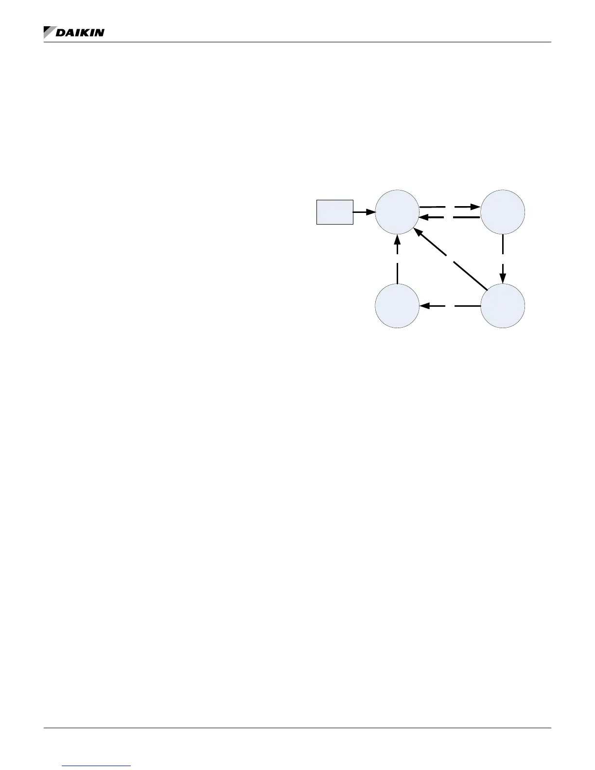
Circuit States
The circuit will always be in one of four states:
Off – Circuit is not running
Preopen – Circuit is preparing to start
Run – Circuit is running
Pumpdown – Circuit is doing a normal shutdown
Transitions between these states are shown in the following
diagram.
T1 – Off to Preopen
• No compressors are running and any compressor on
circuit is commanded to start (see unit capacity control)
T2 – Preopen to Run
• 5 seconds in Preopen state has passed
T3 – Run to Pumpdown
Any of the following are required:
• Last compressor on circuit is commanded to stop
• Unit State = Pumpdown
• Circuit switch is open
• Circuit mode is disable
• Circuit Pumpdown alarm is active
T4 – Pumpdown to Off
Any of the following are required:
• Evaporator Pressure < Pumpdown Pressure Value
• Unit State = Off
• Circuit Rapid Stop alarm is active
T5 – Run to Off
Any of the following are required:
• Unit State = Off
• Circuit Rapid Stop alarm is active
• A low ambient start attempt failed
PREOPENOFF
PUMPDOWN
RUN
POWER
ON
T1
T6
T2
T3
T4
T5