5 Electrical installation
Installation manual
10
ETVH/X16S18+23DA6V+9W(G)
Daikin Altherma 3 H HT F
4P586454-1 – 2019.07
Item Description
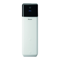
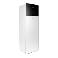
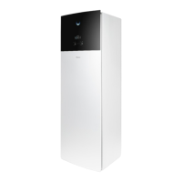
Heat pump convector See:
▪ Installation manual of the heat
pump convectors
▪ Addendum book for optional
equipment
Wires: 4×0.75mm²
Maximum running current: 100mA
For the main zone:
▪ [2.9] Control
▪ [2.A] Thermostat type
For the additional zone:
▪ [3.A] Thermostat type
▪ [3.9] (read-only) Control
Remote outdoor
sensor
See:
▪ Installation manual of the remote
outdoor sensor
▪ Addendum book for optional
equipment
Wires: 2×0.75mm²
[9.B.1]=1 (External sensor =
Outdoor)
[9.B.2] Ext. amb. sensor offset
[9.B.3] Averaging time
Remote indoor sensor See:
▪ Installation manual of the remote
indoor sensor
▪ Addendum book for optional
equipment
Wires: 2×0.75mm²
[9.B.1]=2 (External sensor = Room)
[1.7] Room sensor offset
Human Comfort
Interface
See:
▪ Installation and operation manual of
the Human Comfort Interface
▪ Addendum book for optional
equipment
Wires: 2×(0.75~1.25mm²)
Maximum length: 500m
[2.9] Control
[1.6] Room sensor offset
LAN adapter See:
▪ Installation manual of the LAN
adapter
▪ Addendum book for optional
equipment
Wires: 2×(0.75~1.25mm²). Must be
sheathed.
Maximum length: 200m
See below ("LAN adapter – System
requirements").
LAN adapter – System requirements
The requirements posed on the Daikin Altherma system depend on
the LAN adapter application/system layout (app control, or Smart
Grid application).
App control:
Item Requirement
LAN adapter software It is recommended to ALWAYS keep the
LAN adapter software up-to-date.
Unit control method On the user interface, make sure to set
[2.9]=2 (Control = Room thermostat).
Smart Grid application:
Item Requirement
LAN adapter software It is recommended to ALWAYS keep the
LAN adapter software up-to-date.
Unit control method On the user interface, make sure to set
[2.9]=2 (Control = Room thermostat).
Domestic hot water
settings
To allow for energy buffering in the domestic
hot water tank, on the user interface, make
sure to set [9.2.1]=4 (Domestic hot water
= Integrated).
Power consumption
control settings
On the user interface, make sure to set:
▪ [9.9.1]=1 (Power consumption control
= Continuous)
▪ [9.9.2]=1 (Type = kW)
5.2.1 To connect the main power supply
1 Open the following (see "3.2.1To open the indoor unit"[44]):
1 Top panel
2 User interface panel
3 Upper switch box cover
2 Connect the main power supply.
In case of normal kWh rate power supply
Interconnection
cable (=main
power supply)
Wires: (3+GND)×1.5mm²
—
 Loading...

