5 Electrical installation
Installation manual
13
ETVH/X16S18+23DA6V+9W(G)
Daikin Altherma 3 H HT F
4P586454-1 – 2019.07
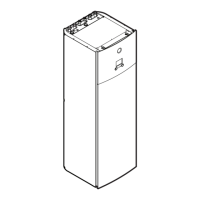
1 Top panel
2 User interface panel
3 Upper switch box cover
2 Connect the valve control cable to the appropriate terminals as
shown in the illustration below.
NOTICE
Wiring is different for a NC (normally closed) valve and a
NO (normally open) valve.
B
A
B
21 28
X2M
B
21 29
X2M
NO
NC
3 Fix the cable with cable ties to the cable tie mountings.
5.2.4 To connect the electricity meters
Wires: 2 (per meter)×0.75mm²
Electricity meters: 12VDC pulse detection (voltage supplied
by PCB)
[9.A] Energy metering
INFORMATION
In case of an electricity meter with transistor output, check
the polarity. The positive polarity MUST be connected to
X5M/6 and X5M/4; the negative polarity to X5M/5 and
X5M/3.
1 Open the following (see "3.2.1To open the indoor unit"[44]):
1 Top panel
2 User interface panel
3 Upper switch box cover
2 Connect the electricity meters cable to the appropriate terminals
as shown in the illustration below.
3 Fix the cable with cable ties to the cable tie mountings.
5.2.5 To connect the domestic hot water pump
Wires: (2+GND)×0.75mm²
DHW pump output. Maximum load: 2A (inrush), 230VAC,
1A (continuous)
[9.2.2] DHW pump
[9.2.3] DHW pump schedule
1 Open the following (see "3.2.1To open the indoor unit"[44]):
1 Top panel
2 User interface panel
3 Upper switch box cover
2 Connect the domestic hot water pump cable to the appropriate
terminals as shown in the illustration below.

 Loading...