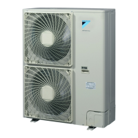
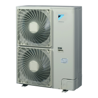
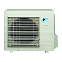
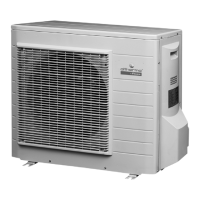
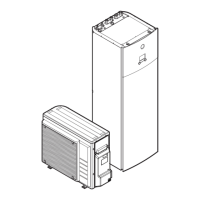
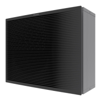
ERHQ011~016BAV3+W1 + ERLQ011~016CAV3+W1
Outdoor unit for air to water heat pump
4PW57794-1 – 08.2010
Installation manual
8
4.4. Functional diagram ERLQ_V3+W1
R2T
R3T
R6T
10
1
6
5
4
3
16
15
7
8
9
12
14
14
13
2
10
11
Y1E
19
Y3S
17
Y3E
Y1S
M1F-M2F
M1C
E1HC
S1NPH
S1PH
18
R1T
R4T
R5T
1 Indoor unit EKHBH/X016 15 Crank case heater
2 Outdoor unit 16 Fan motor
3 Heat exchanger 17 Electronic expansion valve (injection)
4 Service port 5/16" 18 Capillary tube
5 Compressor 19 Solenoid valve (hot gas pass)
6 Accumulator R1T Thermistor (air)
7 Pressure sensor R2T Thermistor (discharge)
8 High pressure switch R3T Thermistor (suction)
9 4-way valve R4T Thermistor (heat exchanger)
10 Filter R5T Thermistor (heat exchanger middle)
11 Electronic expansion valve (main) R6T Thermistor liquid
12 Field piping Ø9.5 Heating
13 Field piping Ø15.9 Cooling
14 Stop valve (with service port 5/16")

 Loading...


