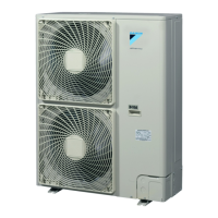
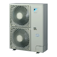
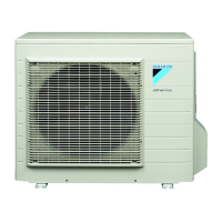
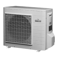
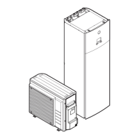
ERHQ011~016BAV3+W1 + ERLQ011~016CAV3+W1
Outdoor unit for air to water heat pump
4PW57794-1 – 08.2010
Installation manual
20
■ As this unit is equipped with an inverter, installing a phase
advancing capacitor not only will deteriorate power factor
improvement effect, but also may cause capacitor abnormal
heating accident due to high-frequency waves. Therefore, never
install a phase advancing capacitor.
14.2. Connecting power supply and interunit wiring
■ Secure the earth wire to the stop valve attachment plate so that
it does not slide.
■ Secure the earth wire to the stop valve attachment plate one
more time along with the electric wiring and the inter-unit wiring.
■ Lay the electrical wiring so that the front cover does not rise up
when doing wiring work and attach the front cover securely.
■ When cables are routed from the unit, a protection sleeve for the
conduits (PG-insertions) can be inserted at the knockout hole.
(See figure 3)
When you do not use a wire conduit, be sure to protect the wires
with vinyl tubes to prevent the edge of the knockout hole from
cutting the wires.
■ Follow the electric wiring diagram for electrical wiring works
(delivered with the unit, located at the inside of the front plate).
■ Form the wires and fix the cover firmly so that the cover may be
fit in properly.
14.3. Precautions on wiring of power supply and
inter-unit wiring
■ Use a round crimp-style terminal for connection to the power
supply terminal board. In case it cannot be used due to
unavoidable reasons, be sure to observe the following
instruction.
- Do not connect wires of different gauge to the same power
supply terminal. (Looseness in the connection may cause
overheating.)
- When connecting wires of the same gauge, connect them
according to the below figure.
■ Use the correct screwdriver to tighten the terminal screws.
Small screwdrivers can damage the screw head and prevent
appropriate tightening.
■ Over-tightening the terminal screws can damage the screws.
■ See the table below for tightening torques for the terminal
screws.
CAUTION
Be sure to install the required fuses or circuit breakers.
1 Switch box
2 Stop valve attachment plate
3 Earth
4 Cable tie
5 Wiring between units
6 Power supply and earth wiring
Only if bottom plate heater applicable (optional for ERHQ)
7 Bottom plate heater cable
8 Power supply of bottom plate heater (from indoor unit)
ERLQ units control the bottom plate heater internally (no
field wiring applicable).
4
3
3
3
2
1
V3 W1
5
8
6
4
7
5
8
6
7
1 Power supply, earth wiring, and if applicable: bottom plate heater
wire
2 Wiring between unit
1 Wire
2 Bush
3 Nut
4 Frame
5 Hose
A Inside
B Outside
Tightening torque (N•m)
M4 (X1M) 1.2~1.8
M5 (X1M) 2.0~3.0
M5 (EARTH) 3.0~4.0
1
2
1
2
1
2
123
1 Round pressure terminal
2 Cut out section
3 Cup washer
 Loading...