EDUS39-605 Control Devices
Controls 5
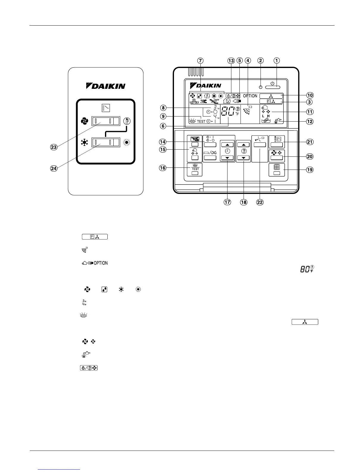
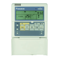
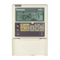
2.1.5 Remote Controller and Changeover Switch: Name and Function of Each Switch and
Display
1. ON/OFF button
Press tto start; press again to stop system.
2. Operation lamp red
The lamp lights during operation.
3. Display indicates changeover under control
It is impossible to changeover heat/cool with the remote controller when this icon is displayed.
4. Display indicates air flow flap
Refer to the chapter Operation procedure - Adjusting the air flow direction.
5. Display indicates ventilation/air cleaning
6. Shows that optional accessories total heat exchange and/or air cleaning unit are operating. Display set
temperature
Shows the temperature set.
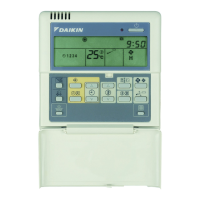
7. Display
""
""
""
""
operation mode
. Shows current operation mode.
8. Display programmed time
Shows the programmed time of the system start or stop.
9. Display indicates inspection/test operation
10.When the inspection/test operation button is pressed, the display indicates current mode. Display
indicates under centralized control
Indicates system is under centralized control. This is not a standard specification.
11.Display indicates fan speed
Indicates fan speed selected.
12.Display indicates it is time to clean air filter
Refer to the indoor unit manual.
13.Display indicates defrost/hot start
Refer to the chapter Operation procedure - Explanation of heating operation.
14.Timer mode start/stop button
Refer to the chapter Operation procedure - Programming start and stop of the system with timer.Timer on/off button
Refer to the chapter Operation procedure - Programming start and stop of the system with timer.
15.Inspection/test operation button
Only used by qualified service persons for maintenance purposes.
16.Programming time button
Program start and/or stop time.
17.Temperature setting button
Set the desired temperature.
18.Filter sign reset button
TEST